


I hope to make a digital tachometer and expect to use the stock tach signal. What sensor sends the tachometer signal? Crankshaft sensor?
Actually, not a digital Tach, an LED tach like the ZX-10. Too late to rename this thread. 
* Last updated by: Rook on 6/19/2018 @ 10:52 PM *
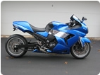
'08 MIDNIGHT SAPPHIRE BLUE Now Deceased