


Clutch Springs, Spring Plate and Clutch Pack Removal
If you suspect that your clutch plates may wearing out, you will need to remove the springs and spring plate to measure the exact clutch pack assembly height. You will also need to remove the clutch plates to inspect each one (see CLUTCH PACK INSPECTION).
Engines that are modified or boosted may require a clutch spring upgrade to prevent the additional horsepower from causing the clutch to slip. Special installation instructions for clutch spring upgrades are discussed in step 11 of this tutorial.
To avoid introducing fibers that may clog oil passages in the engine, I suggest not wiping the inside of the engine case or any of the clutch parts at all. If it’s absolutely necessary to wipe any parts (probably only to mark them with Sharpie), a micro fiber or other synthetic fiber cloth would be better than a regular cotton rag.
If you want to reassemble a clutch pack exactly as it was before removal, it is imperative to mark the order and orientation of all parts. A Sharpie marker works well for marking parts but the engine oil on the parts will make it come off at the slightest touch. You need to keep an eye on marks you made in Sharpie and redo them if necessary.
The clutch pack is the most complicated part of the clutch when it comes to matching disassembly precisely to reassembly. After disassembling and reassembling the entire clutch, I have my doubts as to whether anyone has done this for the first time without getting at least one or two parts put together differently than they came out. If you make an error in your markings, I would not worry about it too much. I think some people don’t bother to keep track of any exact markings at all and the clutch works fine. As long as the inner plate and the outer plate go back in the right order, the clutch will still work even if some of the plates have been flipped over so the IN side now faces OUT. Where it is imperative that a part be reinstalled in an exact order or orientation, I have noted that.
Since this is the beginning of clutch disassembly, I will include the following description of how a motorcycle clutch works. It’s a good thing to understand and if you disassemble the clutch further, the info will be handy.
How a Motorcycle Clutch Works
The clutch allows power from the motor to be disconnected from the rear wheel. If power could not be disconnected from the rear wheel, the engine would stall when the rear wheel stopped. The clutch engages and disengages power to the gearbox allowing the bike to take off and shift gears smoothly and also stop while in gear.
The clutch is an enclosed drum situated on its side with the input shaft running axially through its center. The drum is formed by the clutch basket which has an open front and a closed back (like the sides and bottom of a basket) and the clutch spring plate which fits inside the open end of the basket forming a cover. Another drum called the clutch hub is inside of the basket. It is situated with the shaft running through its center axis and with its open end facing outward like the basket. The clutch is two cylinders, one inside the other, both situated on their side with a cover over them and a shaft running through their center axis.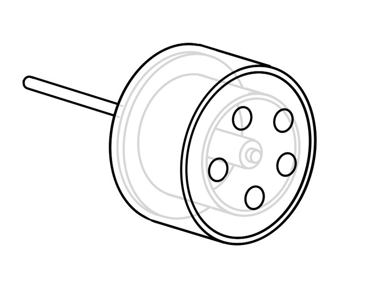
The basket has teeth around its outside perimeter forming a large gear called the primary gear. This gear meshes with another gear on the engine crankshaft. The basket is engaged to the engine by these two gears. Any time the engine is running, the engine is turning the clutch basket.
The hub has splines around its center hole that are engaged with splines on the input shaft running through its center. The input shaft connects the hub to the gear box by these splines. Any time the hub turns, the gearbox also turns. 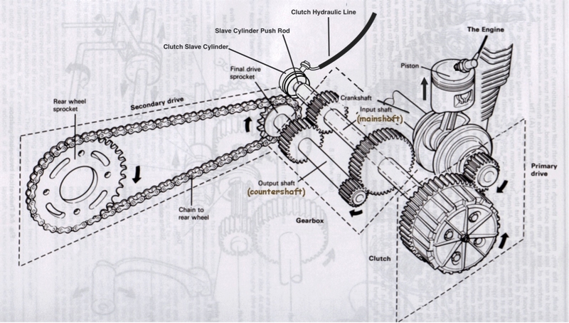
So the engine turns the basket, the basket turns the hub, the hub turns the input shaft which turns the output shaft which transmits power down the final drive to the rear wheel. This is how the clutch works while it is engaged. How does the clutch disengage power from the engine to the rear wheel?
There is a large gap of space between the inside wall of the basket and the outside wall of the hub. This gap is filled by 19 ring shaped plates, together, called a clutch pack. Ten of the plates have fiber pads on both sides. These plates, called friction plates have short tangs protruding around their outer circumference. The tangs fit into channels on the inner wall of the basket so when the basket turns, the frictions must turn with it. The remaining nine plates have a smooth metallic surface. These plates, called steels, have teeth around their inner circumference that fit into splines on the outer wall of the hub so when the hub turns, the steels must turn with it. The steels and frictions overlap in alternating fashion. The steels are engaged to the hub, the frictions are engaged to the basket. While the basket is turned by the engine, the hub tends to maintain relative position to it because the plates stick together by an oil seal. The oil seal is similar to a magnetic force in that the plates are attracted to one another and stick together when they make contact but if they are pulled far enough apart, the force is broken.
The clutch spring plate fits closely to the basket but the two do not touch. The spring plate does however touch the clutch pack. The spring plate has five clutch spring bolts, each fitted with a clutch spring under the head. Each bolt goes through its clutch spring and through the spring plate then threads into a bolt hole in the hub. The clutch springs pull the spring plate tightly against the clutch pack which engages the hub and the basket. The plates grip against one another tightly under the spring pressure and the hub and basket strictly maintain position relative to one another. 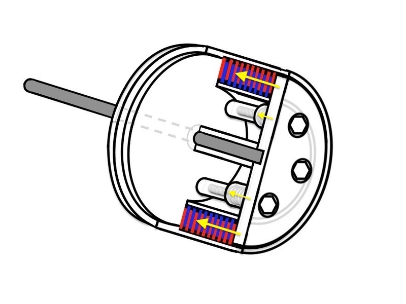
When the clutch lever is pulled, the clutch slave cylinder push rod extends down the center of the hollow input shaft. The extension of the rod pushes against the inside of the spring plate. The clutch springs extend as the spring plate moves away from the clutch pack. Without the compression provided by the spring plate, the frictions and steels will slip while power is delivered to the clutch from the engine. Once the oil seal between the plates is broken, they lose grip. A coat of hot oil fills in between the plates and allows them to glide freely next to one another. The hub and basket may turn independently of one another now.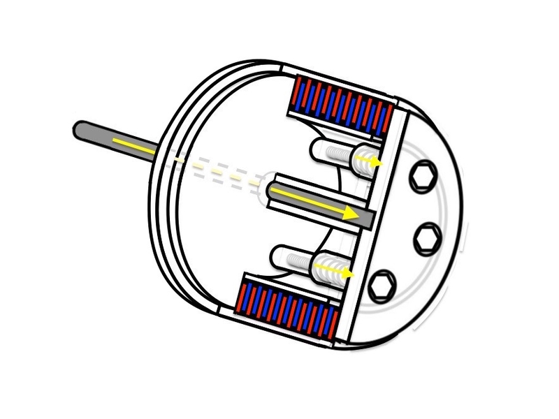
That’s how the clutch works. It basically is a mechanism to connect and disconnect power to the wheel. You can see why it is necessary to engage the clutch at proper speed and engine power. You can also see why a clutch would wear out faster if it is “slipped” at high rpm and how skillfully slipping at high rpm increases power — the engine is allowed to turn faster while it is partially engaged so the engine can take advantage of greater horse power. A hard launch is a balance between increased horse power and decreased power delivery to the wheel.
I hope that helps explain if you were perplexed by how a clutch worked as I was. This video also provides a very helpful demonstration.
Tools:
rear stand
book
steering pivot stand
10mm socket
Sharpie marker
masking tape
clean plastic bag
zip tie
clutch ring removal picks
DO FIRST:
Clutch Cover Removal
Removal
1. Lift the bike on a rear stand.
Place the transmission in first or second gear.
Place a book under the rear tire. Lift the front of the bike with a steering pivot stand so that the rear tire contacts the book hard enough to compress the rear suspension about 1.5 inches (depending on your preload setting) from fully open. Do not attempt to compress the suspension too much or it may tip off the stand. I do not advise using a fork lift stand for this. The fork bottoms could get pushed forward off the lifting pins from the increased pressure caused by compression of the rear suspension before the front stand is locked past vertical.
The rear suspension compression will hold the engine from turning when you remove the clutch spring bolts. It also ensures a stand cannot be levered over backward. The exact book thickness will depend on the height of the rear tire after the front is lifted on the front stand. Watch very carefully as you lift the front that the the rear tire does not start to lift the bike off of the stand. If you do not have a rear stand, you may place a padded bar over the swing arm and under a wheel spoke to lock the engine.
You can just put the bike in gear and leave it on the side stand but breaking the bolts will be turning the clutch counterclockwise with turns the wheel and engine forward. Make sure the bike can’t roll forward off the side stand.
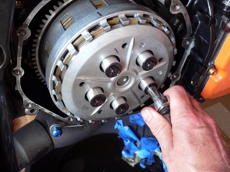
2. Mark the clutch spring bolts, “1, 2, 3, 4, 5” with Sharpie.
Use a 10mm socket to break loose all five clutch spring bolts.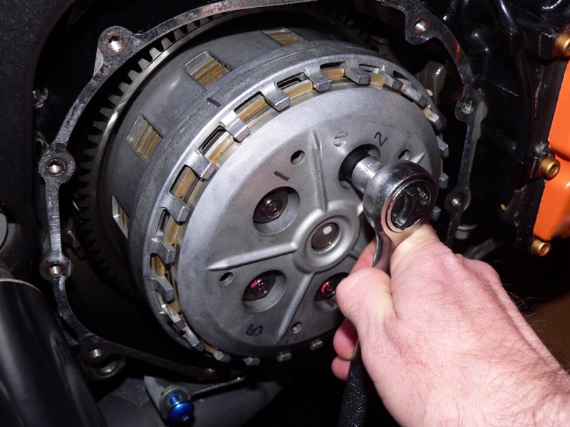
To maintain wear pattern of parts after reassembly, I recommend the use of a Sharpie marker to indicate the exact position of clutch spring bolts in relation to the clutch spring plate wells. Also, the spring plate to the bolt holes in the clutch basket.
3. Thread each of the five bolt heads out of the wells in the clutch spring plate gradually and evenly to avoid binding. 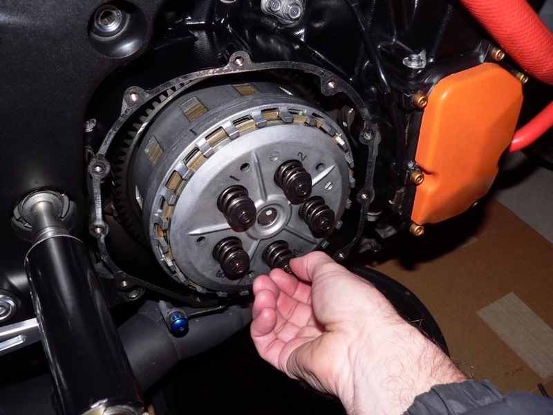
Mark the clutch spring, bolt and washer that comes out of each well, “1, 2, 3, 4 and 5”.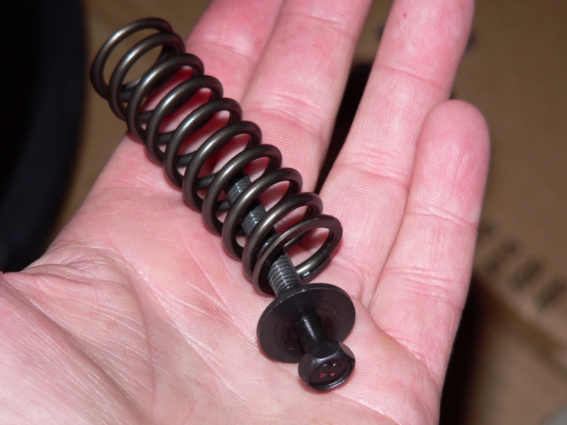
Wrap each spring bolt and washer in masking tape exactly as it came out (with top of spring against bottom of washer) and mark it to its clutch spring plate well.
4. Pull the clutch spring plate out of the clutch hub about 1/16 inch or less. The first few outer plates will probably stick to the inside surface of the spring plate. Press them back into the stack with your finger tips as you carefully remove the spring plate. 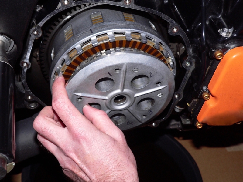
If any plates come all the way out of the groves in the clutch hub and basket, it will be difficult to put them back in the exact position they came from. If you want to avoid the possibility of establishing a new wear pattern, it’s best to put everything back exactly as it came out.
Mark the clutch spring bolt holes “1, 2, 3, 4 and 5” according to the wells they were mated to.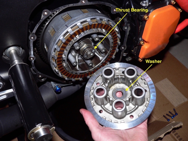
The thrust bearing washer will probably stick to the inside of the spring plate.
5. Mark one finger on the basket and one tooth on the hub. Put a mark to each side of the marked finger on the edge of each fiber plate before removing it. Put a mark to each side of the hub spline you have marked on the edge of each steel before removing it.
Press your fingers against the stack through the rectangular windows in the basket to pull the stack forward. Remove each clutch plate individually after marking it and place them outer face down in a clean plastic bag. In this way, the outermost plate will now be outer face down at the bottom of the stack and the innermost plate will be outer face down on top.
It is important that you maintain the proper front to back order of the plates. The innermost and outermost plates must go back in there spots for proper function. Fold closed the plastic bag the clutch plates were placed in and immediately mark the bag, INSIDE and OUTSIDE so you will know the proper order and orientation of the plates.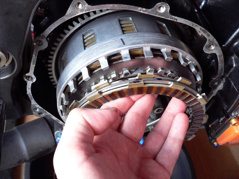
Make two Sharpie marks on each plate (one mark to each side of the basket finger or hub spline you have marked) and there will no problem installing the plates exactly as they came out. There are no manufacturer markings on the friction plates to identify a particular side that should face in or out. On one side of each friction plate, there are numbers stamped on two of the tangs. Some of my plates were factory installed with the numbers in and others out. I guess if I were to install new frictions, I would place the stamped numbers all facing the same direction to make identifying the orientation easier in the future.
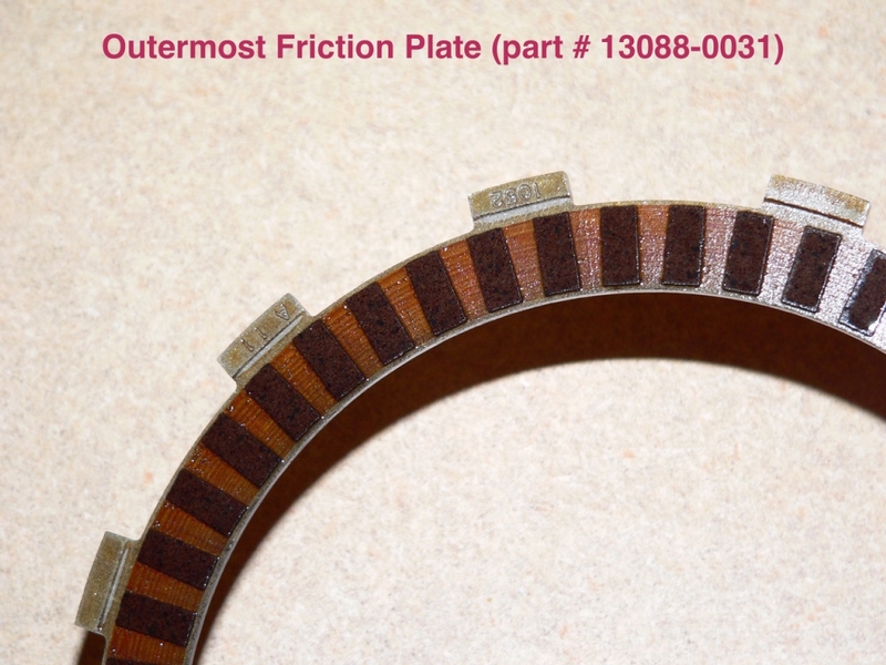
The outermost friction plate has pads that span from outside diameter to the inside diameter.
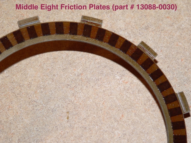
The middle eight friction plates have smaller fiber pads.
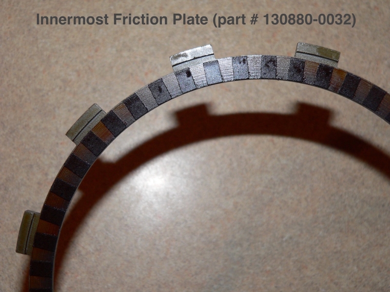
The innermost friction plate has a larger inside diameter.
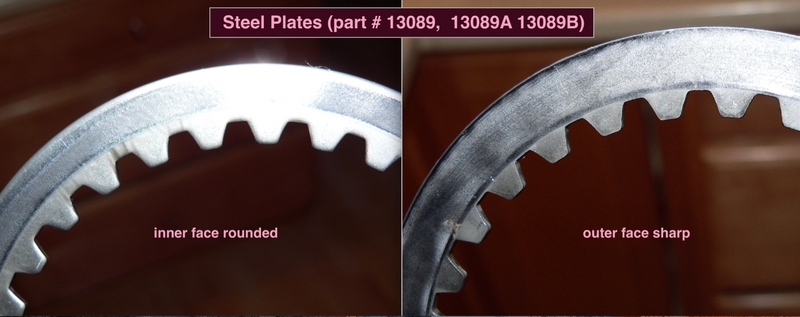
All steel plates have a face with rounded edges as though the blanks were stamped from that side. The other face has a flat, crisp edge. All of my steels had the round edged side facing inward.
If you don’t care to be so careful about exact positioning of the clutch pack, you can slide a zip tie into one of the open tooth spaces on the clutch hub and simply pull the whole pack forward onto your finger (careful, it’s not light). If you mark which open tooth you inserted the zip tie to and pull the pack out before any plates slip out of position, you will probably achieve the same result as removing each plate individually. Lock the zip tie immediately but not tight or the fiber pads may deform. Mark the bag INNER and OUTER after placing the clutch pack inside.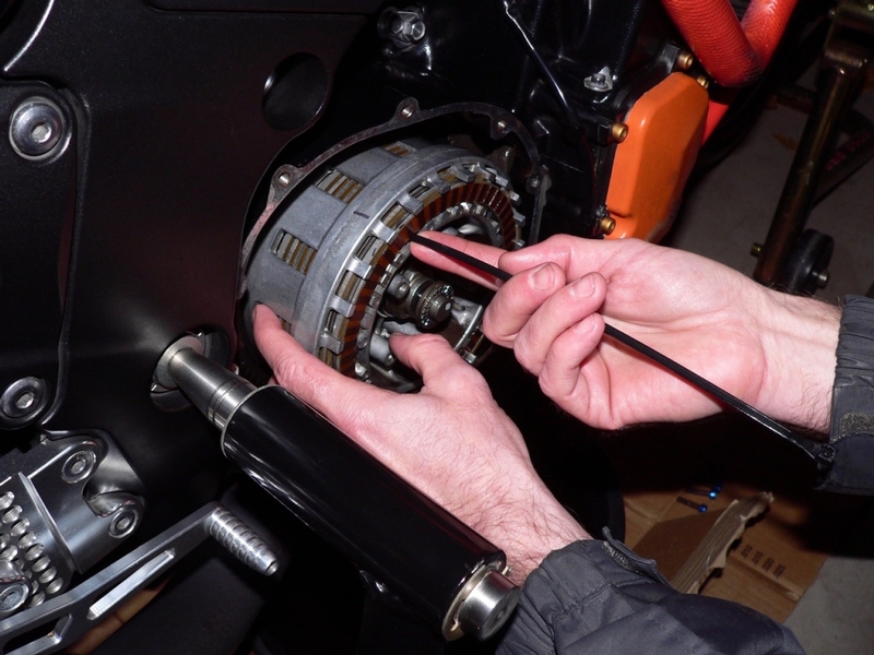
Now that there is no spring tension on the clutch pack, the engine holds the clutch basket in its present position and the wheel under load of the suspension holds the hub. If the wheel or hub turns, the orientation of the hub and the basket will be changed. This is not such a serious matter since the orientation of the hub and basket change all of the time when operating the motorcycle. The orientation of the basket and hub can be put back where it started. The Steels will be installed according to the mark on the hub tooth and the frictions according to the mark on the basket finger regardless of the orientation of the basket and hub.
6. There should be 19 plates in all, 10 frictions and 9 steels. In addition, there are 2 more rings on the friction surface of the hub (red arrow) that probably will not come out. These are the anti-judder spring which is a cambered ring (blue arrow) and beneath it, the anti-judder spring seat which is a large flat washer. Both of these rings will come out easily with the clutch hub if you remove that (see Clutch Hub and Basket Removal, step 12).
If you are only removing the clutch plates, you may wish to also remove the judder spring and seat for inspection. You may be able to reach through the rectangular holes in the hub to pull the seat and spring forward with your fingernails or else use clutch ring removal picks to extract these.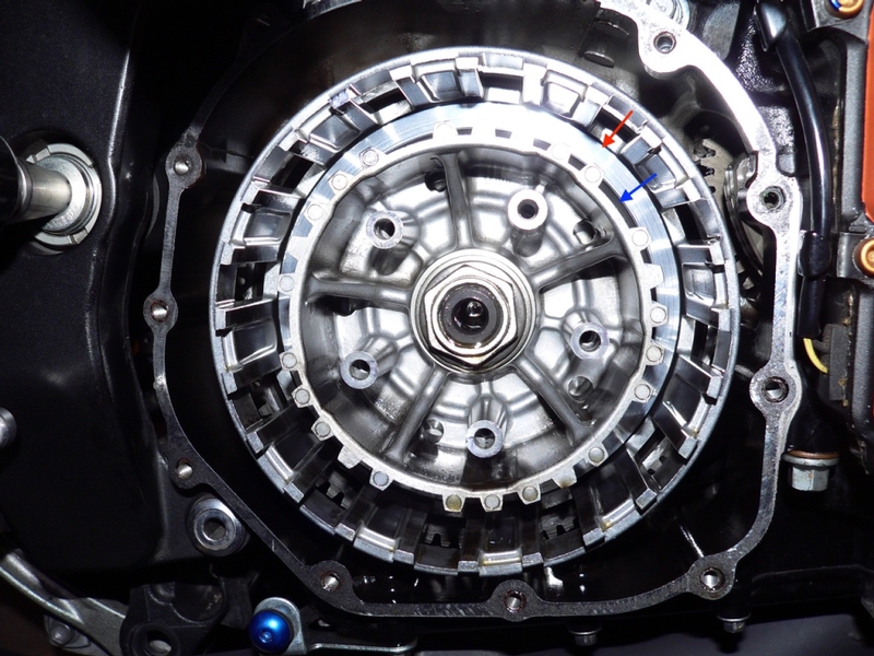
Installation
7. Check the clutch pack height (see CLUTCH PACK INSPECTION, steps 4 through 9)
and adjust it with different sized steels if necessary.
Soaking is optional if reinstalling used plates that are already impregnated with oil but it is necessary to avoid plate seizure any time dry plates are installed. If the plates are new or the old ones have been out of oil for some time, soak them in oil before you install them. Black Sharpie holds up remarkably well in oil as long as it does not rub against anything but wrap a thin soft wire around each plate where the markings are to be sure. To avoid cutting or deforming the fiber pads, wrap the wire between the pads, not over.
Place the plates in proper order and orientation in a 1 gallon zip lock bag. During this process, I also made a notation of whether the stamped number on each fiber was facing inside or outside so this could not be confused as the fibers were handled during installation. Pour in about one quart of oil and let the plates soak for at least 24 hours. 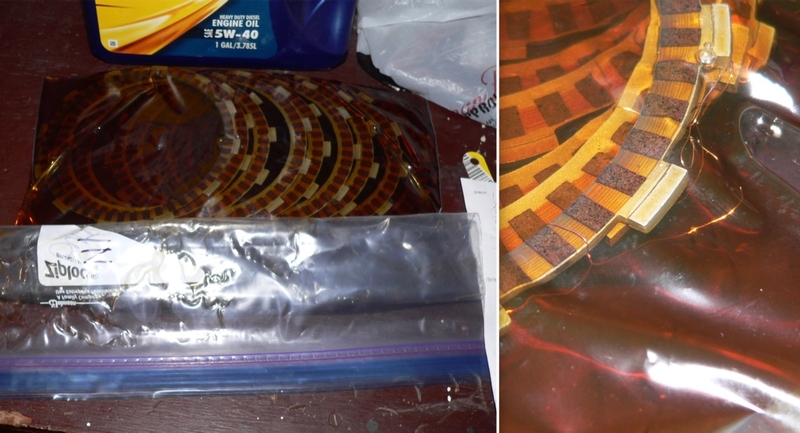
If you are installing new springs, you should note their free length (see CLUTCH INSPECTION, step 10) for future reference.
8. Make sure the anti-judder spring seat (B) is installed first. Then the anti-judder spring (A) should be installed with the larger diameter facing out to the RH side (see photo, step 12 of Clutch Hub and Basket Removal).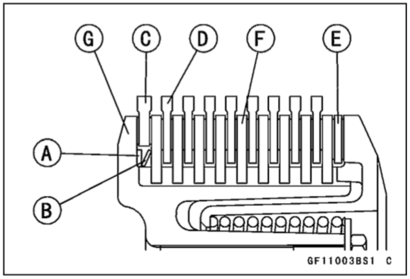
If wire was used to mark the plates before they soaked in oil, wipe a spot on the plate and remark it if necessary before removing the wire and installing each plate. Install the inner fiber then its steel, the middle eight fibers with their adjacent steels and the outer fiber plate. All plates should be installed in the same order and orientation to one another and the markings on the clutch hub and basket made in step 5.
The outermost plate must be installed offset from all the other fibers. Its tangs are installed to the outer grooves in the clutch basket rather than the slots between the fingers.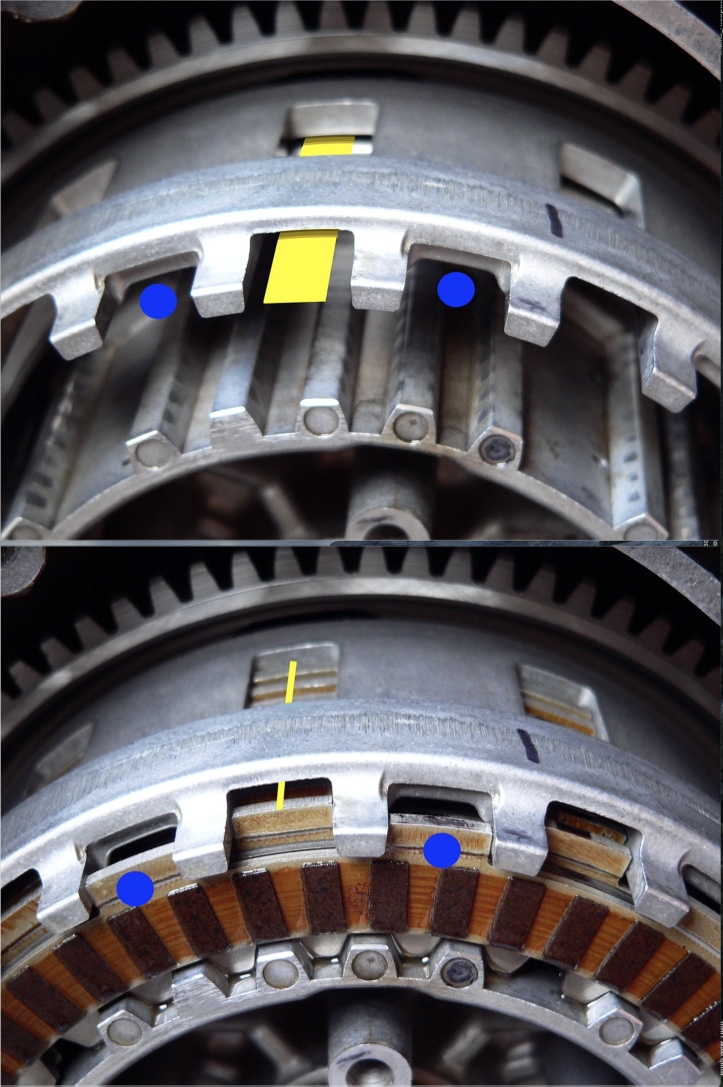
Except for the outermost plate, all fiber plates are installed with their tangs held within the slots that match up to the windows in the clutch basket (yellow line). The outermost fiber plate is installed to the grooves between the windows (marked by the blue dots) instead. The outer plates will fly out when the clutch is disengaged if the clutch pack is not installed this way.
9. Oil the thrust bearing washer and install it to the thrust bearing in the same orientation as it came out. There may be a wear ring that matches the needle bearings.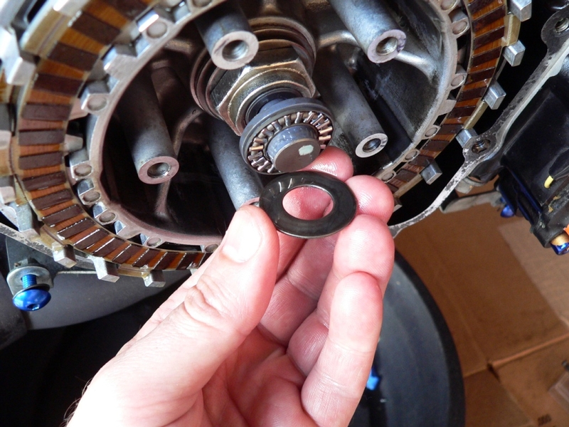
Install the clutch spring plate according to the marks on the bolt holes in the clutch hub (see step 4).
You may notice a large gap between the spring plate and the clutch pack. Press in gently and lift under the spring plate. It should pop into position under the fingers of the clutch basket.
The thrust bearing will also need to pressed back in against the clutch slave cylinder hydraulic pressure to fit the spring plate tightly against the clutch pack. 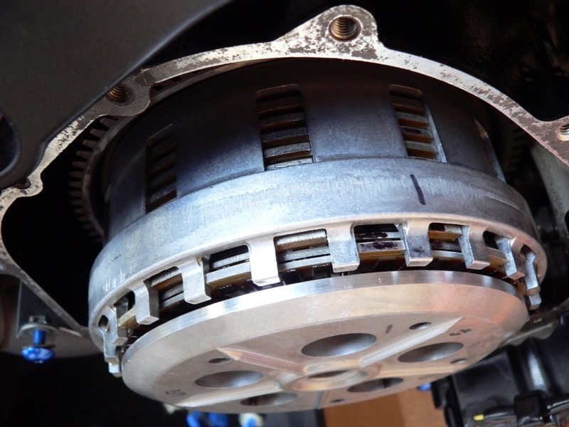
10. Oil the springs before installing. Install each clutch spring, clutch spring bolt and washer in the same orientation as it was removed in step 3 and to the well it was marked to in step 2. Do not oil the bolt threads. You might want to clean both male and female threads before installing the bolts. Torque specs are normally not for oiled threads unless specified.
If aftermarket spring spacers are being installed, oil each spacer and place it after the spring is inserted to the well and then install the bolt.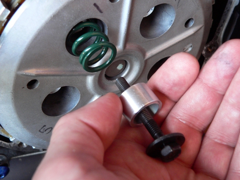
11. Thread the spring bolts in finger tight evenly, each a little at a time.
Verify that the clutch spring plate is positioned properly as described in step 9.
Use a 10 mm socket to draw the bolts up evenly, then an accurate torque wrench (see TORQUE WRENCH CALIBRATION ) tightening each bolt a little at a time until the proper torque is achieved on all.
Torque - Clutch Spring Bolts: 9.0 Nm (0.92 kgf m, 80 in lb)
13. Lower the steering pivot stand.
Remove the book from under the rear tire and lower the rear stand.
* Last updated by: Rook on 2/17/2018 @ 5:51 PM *