


Throttle Bodies Subharness Removal
There will probably never be a need to remove the throttle bodies sub harness completely. All you need to do to install a Power Commander or to remove the throttle bodies assembly is to disconnect the main lead connectors. Other than those, only one lead connector will need to be removed if it is necessary to test it’s electric signal.
There are lead connectors that go to the primary and secondary throttle position sensors. I believe I was advised to never remove those unless absolutely necessary because the sensors will become out of calibration. More likely, the sensor would need recalibration if its positioning is altered by removing or loosening the screw that secures it to the throttle bodies. I wouldn’t mess with the TPSs or leads unless you need to.
Do First:
Remove the Foremans, Fuel Tank Cover, Ram Air Covers, Fuel Tank Cover, Side Fairings and Lowers (see FAIRINGS REMOVAL).
Disconnect battery negative ground wire (Battery Removal steps 1-3)
Remove the coolant reservoir (see ENGINE COOLANT RESERVOIR, steps 1 and 2) to allow more clearance for the main wiring harness.
Tie the coolant reservoir with a string so that it will not hang on the hoses.
Tools:
8 mm socket/ratchet
bottle cap opener
small flashlight
long, thin, straight slot screwdriver
nail clippers
masking tape and a Sharpie
If you disconnect more than one lead connector, I suggest you mark each for proper reconnection. The diagram below should help you identify the locations of all connectors.
A Main
B1, B2, B3, B4 Fuel Injectors
C Secondary Throttle Position Sensor
D Primary Throttle Position Sensor
E Secondary Throttle Actuator Motor
F Inlet Air Pressure Sensor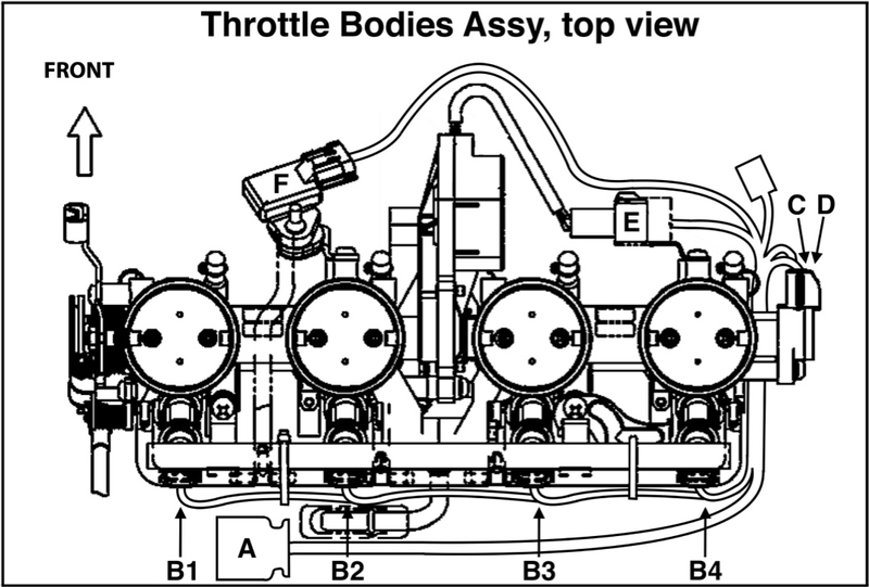
Removal
1. You may find it easier to disconnect the main lead connectors of the throttle bodies sub harness if you remove the bracket which retains the main wiring harness on the left side of bike near the location of the coolant reservoir. Use an 8 mm socket/ratchet to remove the bolt and let the main wiring harness hang to the side.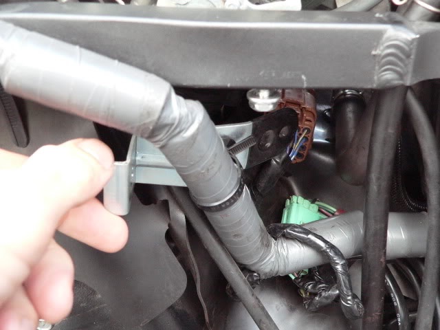
2. Locate the throttle bodies subharness main lead connectors. They are the brown set of cube shaped connectors between the throttle bodies and the fuel tank compartment. 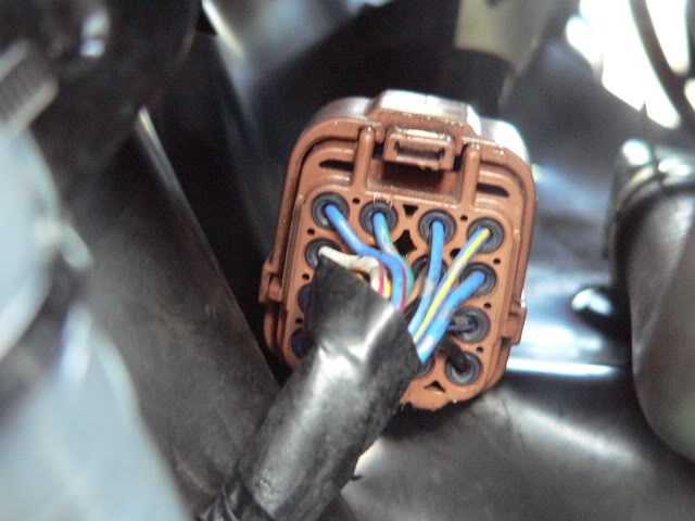
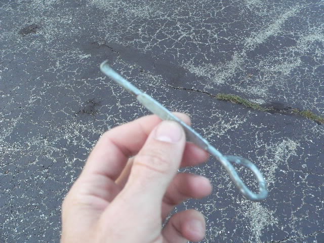
A bottle opener is as good of a tool as I could find to disconnect the main lead connectors. There probably should be a special tool for this task but a bottle opener will get it done.
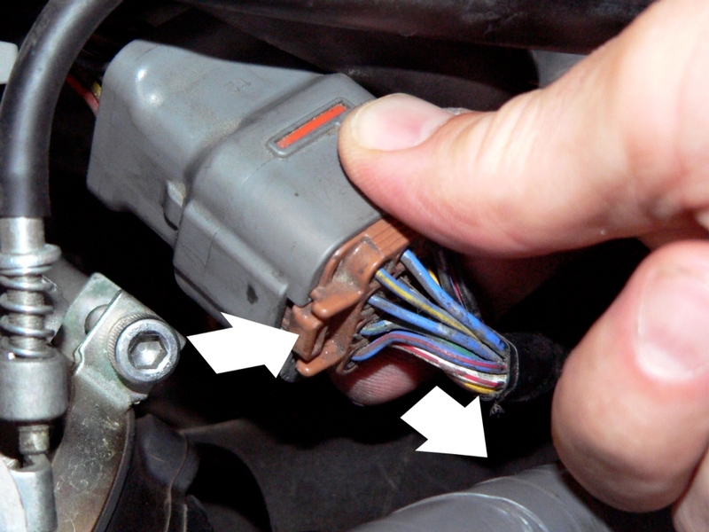
Press down on the tab at the top of the main connectors using the hook end of the bottle cap opener. Use the hook to pull back toward you at the same time. It is not necessary to press down hard. That will not help. The plugs fit extremely tight. Remember, this is plastic so do not pull too hard. Also, if the hook slips, you will bang right against those small wires. I did it a couple times with no damage.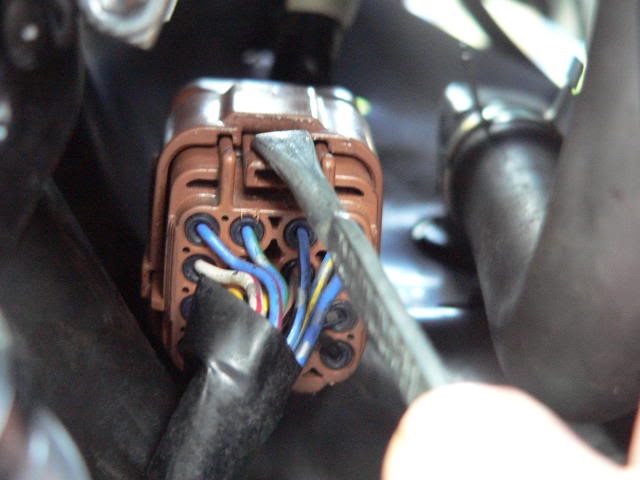
Reach the hook under the connectors and grab onto the ridge. Press up and pull. The plug will separate just a few microns a time. Repeat this tug, top and bottom until you see that the connection has separated about 1 mm. Now the catch should be clear and you will no longer need to depress the tab.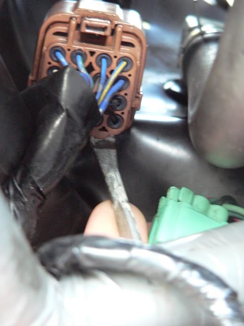
I also used the two small knobs on the top to get a little side to side top pull. Just keep at it, top, bottom, top, bottom………………….. 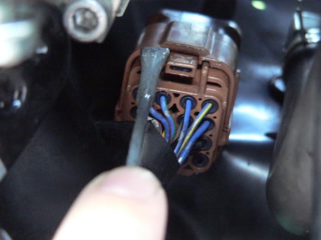
It will eventually pull out all at once. Take your time. It will be very tedious.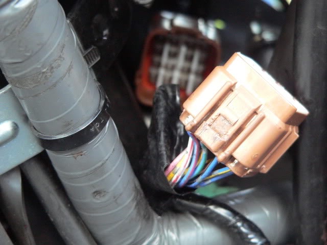
If a Power Commander is installed, there will two be sets of subharness connectors. The pair of subharness connectors that are not bracketed to the engine may be disconnected first (recommended) to free up more space to work on the other connectors.
The subharness connectors that must be disconnected to remove the throttle body assy are the ones with the brown female half and the grey male half. These connectors are fastened to the engine by a bracket.
3. Go to the right side of the engine compartment and locate the back of the fixed
subharness connector under the rubber mat.
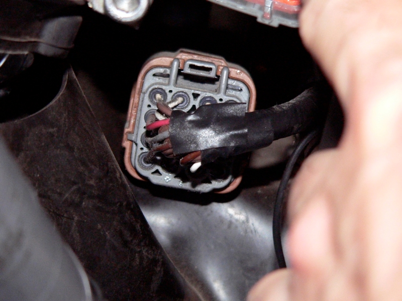
Using a small flashlight, you will see the silver tip of the bracket inside of the thin sleeve at the underside of the brown plastic connector. 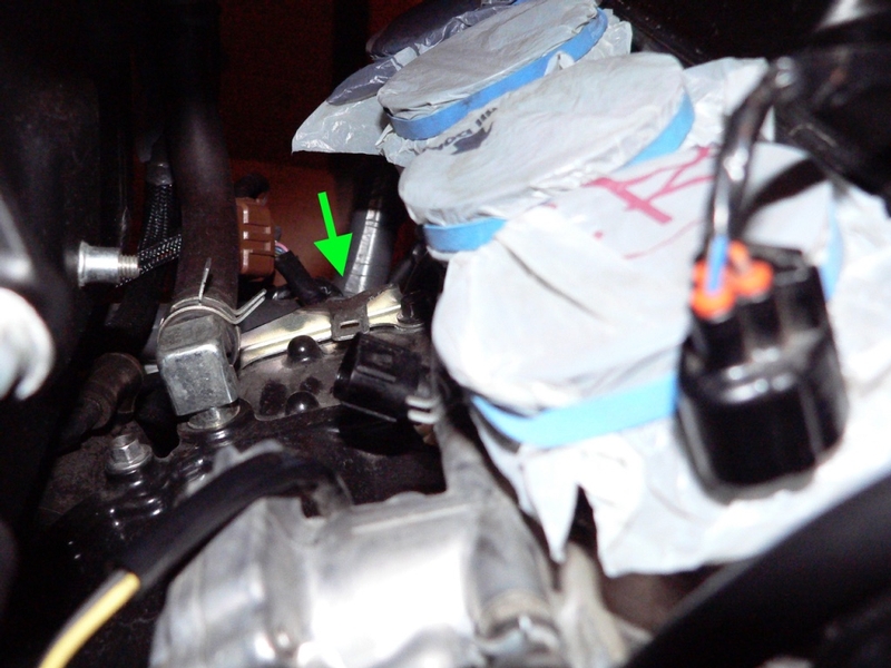
The photo above shows the bracket with the subharness connector removed. The engine heat insulator rubber plate that normally covers the bracket is also removed.
From the RH side, place a long, thin, straight slot screwdriver under the rubber mat and insert the blade between the silver metal end of the bracket and the brown plastic tab right above it. 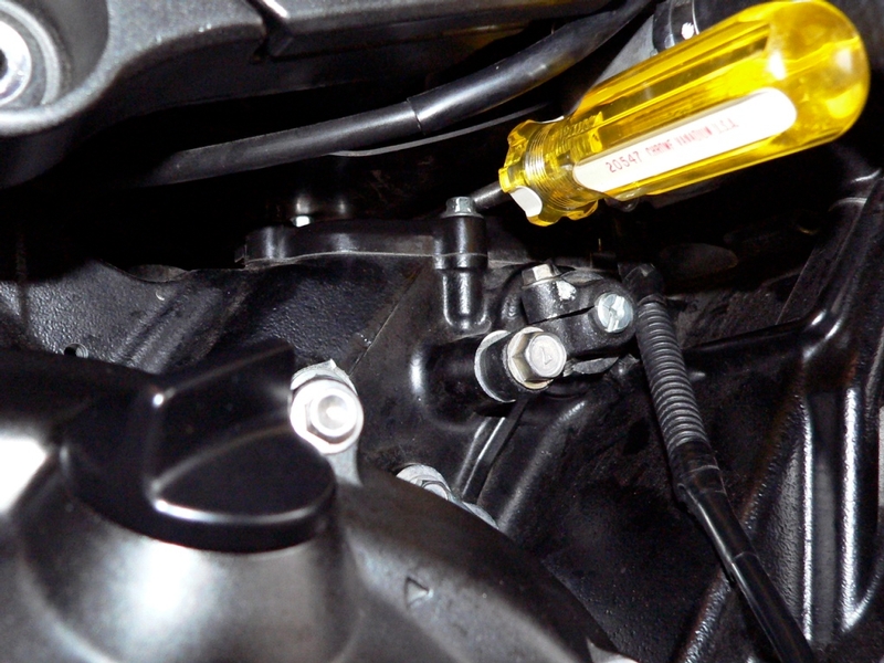
Stand on the LH side of the bike with your chest against the top of the gas tank. Use your right hand to twist the screwdriver prying up gently on the plastic tab to release the catch.
While holding the catch open with the screwdriver, reach into the LH side of engine compartment to press hard against the connector so that it slides to the right and off of the silver metal bracket.
4. Remove fuel injector lead connectors 1, 2, 3 and 4 [blue arrows]. Mark each lead connector on the subharness with masking tape and a Sharpie.
Remove the zip tie [white arrow] that fastens the fuel injector lead and vacuum hose to the fuel rail on the throttle bodies (throttle bodies are removed in the pic). I believe it is reusable zip tie with a tab that can be depressed to unlock the catch. You may need to rotate the catch on the zip tie backward in order to reach it.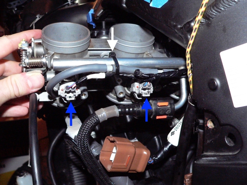
The throttle bodies are pictured removed to show the injector lead connectors.
5. From the RH side of the bike, locate the zip tie [Z] that fastens the sub harness to the crankshaft sensor bracket [B] (crankshaft sensor is removed from bracket in the pic). 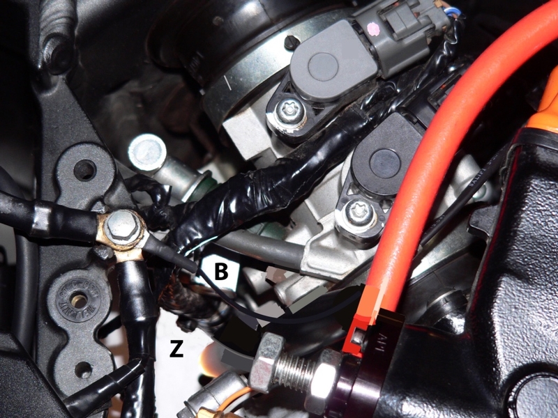
This zip tie is not reusable. Use a pair of nail clippers to cut the catch on the zip tie that retains the throttle bodies wiring harness. DO NOT cut to the bottom of the catch near the wires. Carefully nip the top off of the catch about halfway down its height and this will be enough to cut off the tiny plastic pawl that locks it.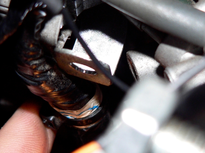
I was able to twist the zip tie counter clockwise with my fingers so the catch is in view.
6. If necessary, remove the secondary throttle position sensor lead connector [grey] and the primary throttle position sensor lead connector [black]. Please read the intro to this tutorial for precautions.
If these lead connectors are removed, mark them with masking tape and a Sharpie for proper reconnection.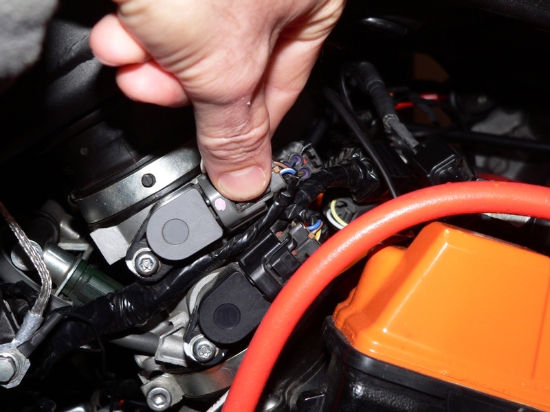
7. From the RH side of the bike, remove the secondary throttle actuator motor lead connector located at the front of the throttle bodies assembly. The subharness lead connector is bracketed to the throttle bodies and you will need to remove it.
Mark the secondary throttle actuator motor connector with tape and Sharpie.
This type of connector usually has a plastic catch that needs to be depressed to release it from a slot in the steel bracket (blue arrows in pic above). I’m sure it’s impractical to free the connector by removing the bracket. The screws on the throttle bodies are always extremely tight.
8. From the LH side of the bike, remove the inlet air pressure sensor lead connector [B]. 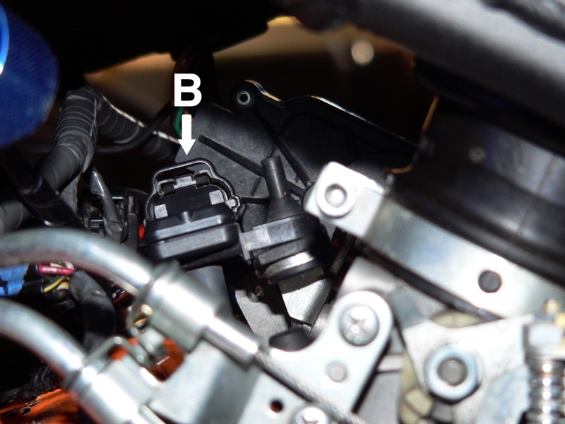
Installation
9. Installation is the procedures in reverse of steps1 through 8.
Push the throttle bodies subharness main wiring harness connector leads together until you feel a definite click of the locking tab. Brown female simply connects to brown male for OEM configuration. Brown female to grey male, grey female to brown male if a Power Commander harness is connected inline of the OEM setup (step 1).
**When the main throttle bodies subharness connectors are connected, be certain that you hear or feel the catch lock. If the catch is not locked, the connectors will vibrate apart causing malfunctions including sudden and complete loss of engine power.
Route all wires and position retainers and lead connectors as they were.
Note the caution about throttle position sensor calibration in the intro of this tutorial.
Replace the non-reusable zip-tie (see step 5)
Connect battery negative ground wire (Battery Removal steps 1 through 3, reverse)
Install the coolant reservoir (see ENGINE COOLANT RESERVOIR, step 3).
Install the Ram Air Covers, Fuel Tank Cover, Side Fairings and Lowers (see FAIRINGS REMOVAL).
* Last updated by: Rook on 12/25/2017 @ 3:27 PM *