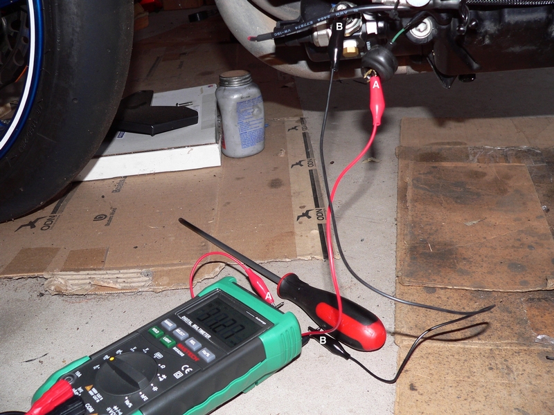


This thread continues from my queries about mini switches. I think we've moved on from that for the time being. I've tested the circuit I plan to use for power and now I'm ready to move ahead with wiring things up.
See the link below for where we left off and also the pages that precede it for info about mini switches and related topics.
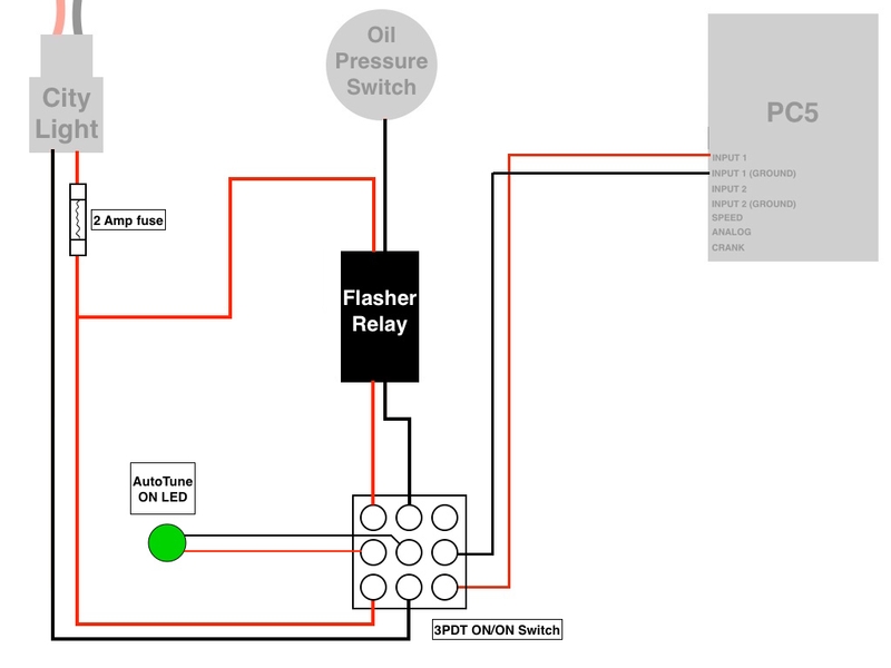
I'm slowly plodding ahead. I have a wiring diagram drawn up showing all 4 switches and how I plan to hook them up but it looks so complicated that I thinK a lot of you might not even want to try to figure it out. One switch a time will be much easier to show and that's how I plan to install them, too.
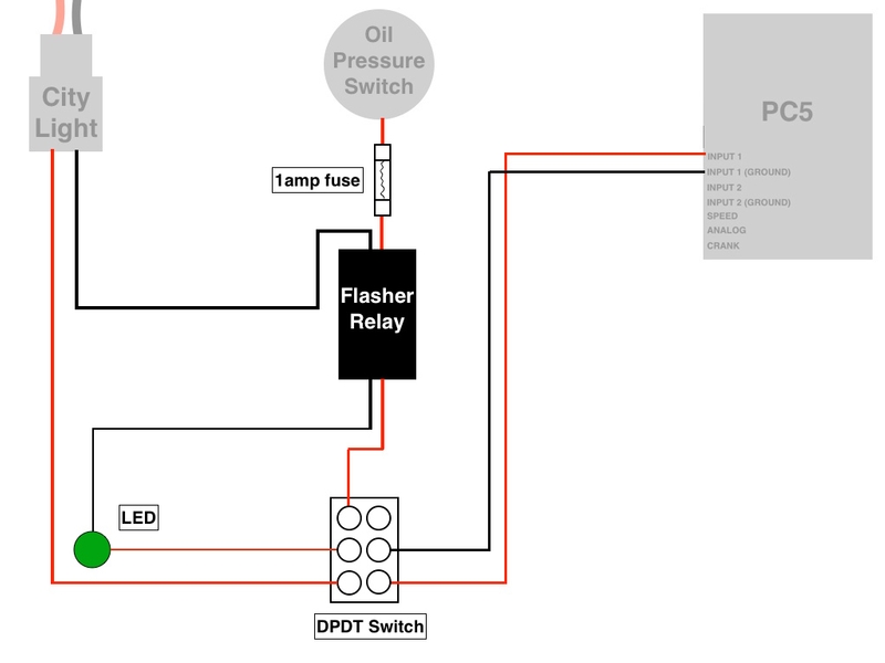
So, how's this look? Will it work? Of course I will test with batteries and also on the bike before I solder or install anything.
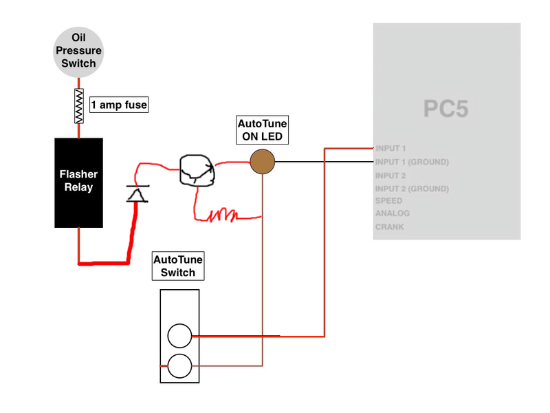
EDIT, 09/0618: No, this won't work for two reasons. #1 the power from the oil pressure switch is pretty low. It is the residual power coming out of the dash oil pressure warning light. It is negative current; not positive. It doesn't matter if it's negative or positive but for all the LEDs I plan to eventually have on the switch panel and dash, there needs to be lot higher amperage. There's only only enough current at the oil pressure switch to light one LED.
#2 The current from the PC5 switch inputs are minuscule. It's not close to enough to light a single LED. This power is also negative (not that matters, it's just too low).
Read further in the preceding posts. Some other important points came up but the setup shown above won't work.
The diagram is pretty clear but below is a written description of what I want--in short, when the ignition is turned ON, the LED should burn steady if Autotune is enabled or flash when AutoTune is not enabled. When the engine is started, the LED should remain burning if AutoTune is ON or it should go out completely if AutoTune is off.
The other LEDs will function in the same way, flashing all at once when the ignition is switched on and going out when the engine starts or if the switch is in the ON position, the LED will just burn steady when the ignition is switched on and stay burning steady when the engine starts.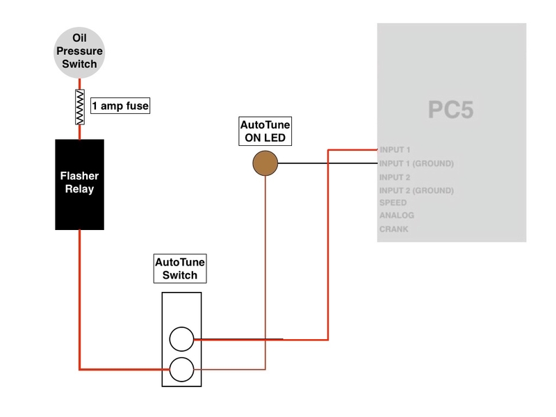
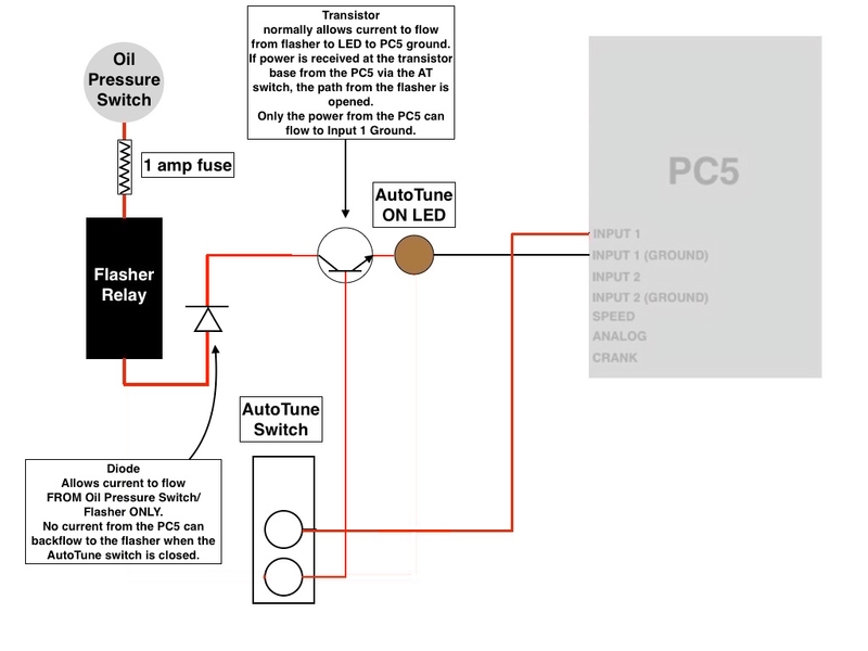
1) AutoTune switch open, ignition ON, green LED flashes: Switch input 1 and input 1 ground of the PC5 are inputs for the AutoTune switch. AutoTune is shut off because the circuit is open between switch input 1 and switch input 1 ground. Oil pressure switch sends current through the fuse and the flasher to the AutoTune switch terminal when the oil pressure light is ON. Power travels from AutoTune switch terminal to green LED. Green LED grounds to the PC5 input 1 ground. When engine starts, oil pressure light shuts OFF, green LED goes out indicating the engine has started and Autotune is shut OFF.
2) AutoTune switch closed, ignition ON: The green LED receives pulses of power from the oil pressure switch and flasher relay and this power goes through the LED and grounds to input 1 ground. However, the green LED does not flash but burns steadily. It is receiving steady power from the PC5 switch input 1 via the AutoTune switch terminals which are closed. Power flows from input 1 through the LED to input 1 ground which completes the circuit for both the green LED and the AutoTune feature. When the engine starts, the green LED continues to burn steady indicating AutoTune is switched ON. The oil pressure switch stops supplying power when the low oil pressure light shuts off.
* Last updated by: Rook on 6/10/2018 @ 3:16 PM *


 So the wire with more power in it will try to climb into the other positive wire and run down it backwards?