


Clutch Hub and Basket Removal
You will probably never need to remove the clutch hub and basket to replace them unless the bike is subjected to extremely harsh use or high mileage. Otherwise the clutch hub and basket are removed to access the components that lay behind them.
If it is necessary to resume work on the clutch at a later time, you should reinstall the clutch cover lightly tightening a few bolts to prevent dust or debris from contaminating the inside of the engine.
As you remove parts, it’s advisable to place them in clean plastic bags so that they do not collect airborne debris. I suggest NOT wiping or cleaning the clutch parts or the inside of the engine case. It is not necessary to remove the black residue caused by normal deterioration of the clutch plates and engine oil.
It is probably not going to make a great deal of difference if you mark every single part for reinstallation. The positions of the clutch hub and basket are constantly changing while the bike is run. The parts that are held in position by splines may benefit more from reassembling exactly as they came out. The first time you disassemble the clutch, I suggest marking everything with a black Sharpie marker as described in the instructions that follow.
You will probably need to rotate the clutch basket and basket in order to remove them. When you do this, it is important to remember to only make the clutch basket turn counterclockwise as viewed facing the RH side (clutch cover side) of the bike. Counterclockwise rotation of the clutch hub turns the motor and wheel in the forward direction. Do not make your motor turn backwards.
If you decide to use an impact wrench to remove the hub nut, DO NOT use a clutch holding tool. Leave all of the clutch plates in and refer to the link to the video in step 1.
Tools:
sheet of plastic
impact wrench (optional)
floor jack or other stable solid object and weights, a chain and hook OR a swing arm pivot stand
clutch holding tool (EBC CT021 Clutch Hub Holding Tool recommended, use one or two)
30 mm impact socket
breaker bar
zip tie
clean plastic bags
Sharpie
two M4 x .7 x 25mm socket head cap screws
fresh oil
clean rags and mineral spirits
new hub nut
molybdenum disulfide grease
Removal
Do First:
Place the transmission in fist or second gear.
Remove Clutch Plates, steps 1 through 6 unless using an impact (see step 1 below).
Line the bottom of the clutch case with a sheet of plastic to catch any small parts that might fall.
1. Remove the Thrust Bearing and pusher by simply pulling the pusher straight out.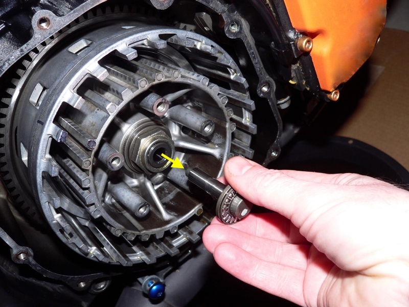
The thrust bearing and pusher are actually two pieces but they will probably be stuck together with oil. Do not separate them unless necessary. Just place them in a clean plastic bag so they cannot accumulate any dust or debris.
It may be necessary to rotate the basket in the next step so that the clutch hub holding tool will engage both the splines on the hub and the fingers on the basket. I have taken the step to mark one tooth on the hub to one finger on the basket so they can be put back in the position they were in when the plates were removed.
I prefer to stay away from using an impact wrench especially for work inside the engine. If you use an impact, beware of blowing dust up with the engine open. Also, do your best to not let the impact bang the engine parts together.
This video shows an easy way to remove the clutch hub nut with an impact before removing the clutch plates. Scroll to 1:28
2. Lower the front of the bike off of the front stand (CLUTCH PLATES REMOVAL, step 1)so that the rear suspension is unloaded.
Engage the clutch hub holding tool(I used the EBC Clutch Holding Tool #CT021)to the splines on the hub and the fingers on the basket. The clutch holding tool must engage the basket and hub at the same time in order to fit. The exact position of the clutch holding tool handle is not important at this time as long as it is more or less between pointing up or toward the back of the bike.
You may adjust the position of the hub so that the hub splines, the fingers of the basket and the clutch holding tool tangs align.
To align the hub to the basket, simply move the rear wheel clockwise a few degrees with your hand. This will turn the transmission which will make the clutch hub turn counterclockwise. You may also just turn the clutch hub by hand or turn the clutch hub nut with a 30 mm socket. Since the clutch plates are removed, the engine is not connected to the hub in any way (except possibly by an oil film) so the basket and engine should remain in position.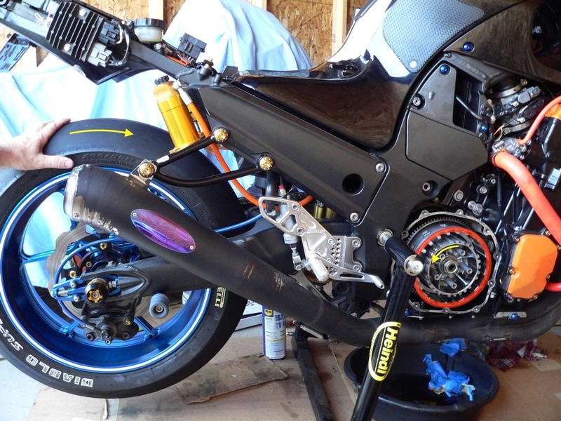
With clutch plates and springs removed, the hub and basket move independently of one another. By turning the rear wheel forward, the hub will turn counterclockwise while the basket remains in position.
If you find it necessary to move the clutch basket, use a clutch holding tool as shown in step 3 and ONLY turn COUNTERCLOCKWISE. The basket, hub and engine will turn in the correct direction at the same time. If you turn the basket too far, continue turning counterclockwise until a suitable position is found. Don’t turn the basket clockwise or the engine will turn backward.
3. Now that the clutch holding tool is fit to the clutch hub and basket, you may turn the handle of the tool counterclockwise (not clockwise) so that it rests against a floor jack or other stable solid object. Do not arrange the handle too far past horizontal or it will be more likely to slip.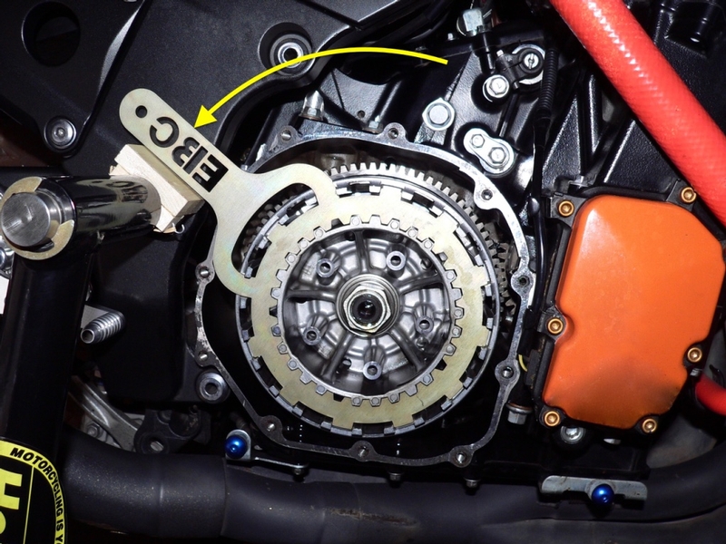
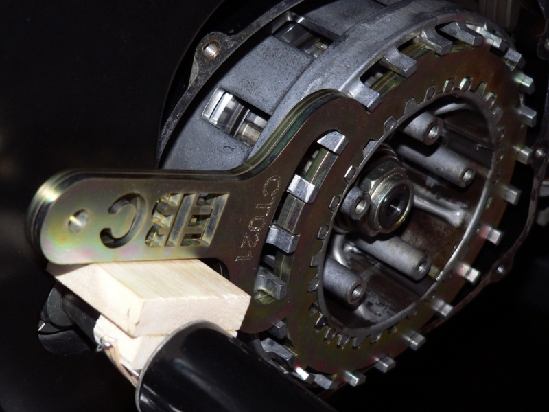
Thinking it would reduce my chance of gouging the hub teeth by half, I used two EBC CT021 Clutch Hub Holding Tools which are as many as will fit. One was doing most of the work but at $18 per tool it was cheap insurance.
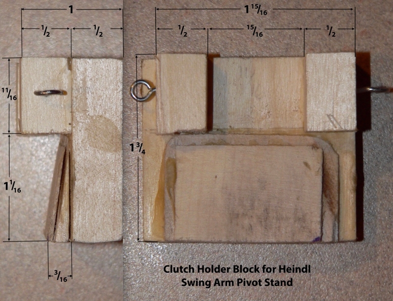
The spike on my Heindl swing arm stand supported the clutch tool handles. I made a wooden block that fits on the tapered spike to create a level surface for both clutch holding tools to rest against.
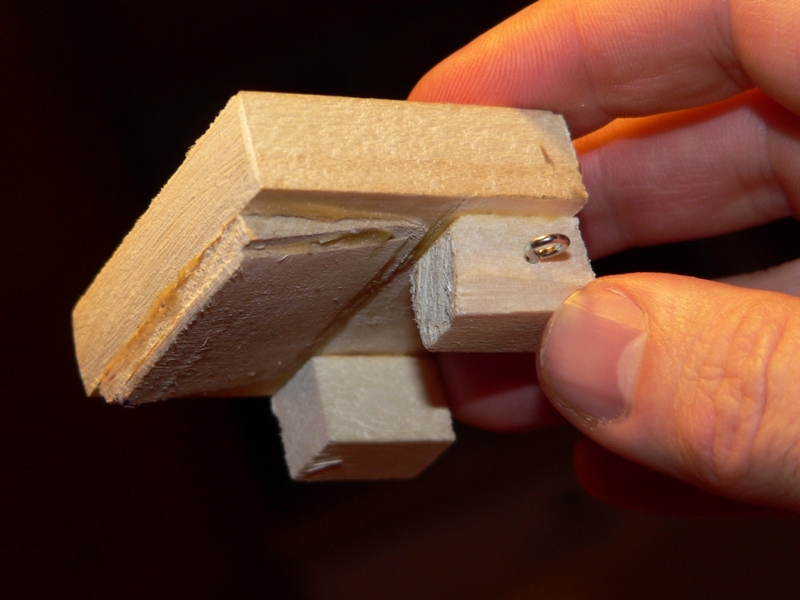
The square dowels are just for positioning of the block and the eye screw and hook are for attaching a rubber band to hold the block to the spike. The sloped surface on the block conforms to the taper of the spike and creates a level surface for the clutch holding tool handles to rest against.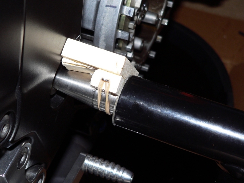
4. Verify that the front wheel is lowered and the rear suspension is unloaded. Place the transmission in Neutral.
If you are using a swing arm pivot stand or any stand that lowers by tilting backward, you will need to put books under the rear wheel so that the stand cannot be levered backward.
Place a 30 mm impact socket with breaker bar on the the hub nut. Vertical will be the position least likely to lever the bike over but being that the leverage is applied at the center of the bike, this danger is minimized.
Turn the breaker bar counterclockwise to break the hub nut free. Be careful, applying gradual torque to feel if the bike tilts on the spool forks or if the stand tilts. Do not wrench the handle abruptly. 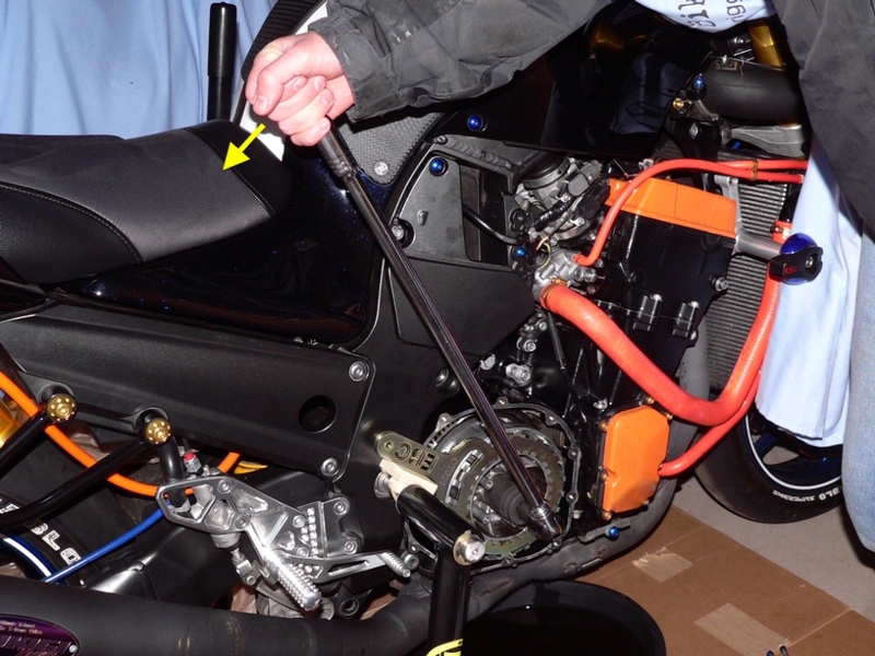
This nut was very hard to break free, even with the breaker bar. I positioned myself opposite of how you see me in the picture above so that I was looking toward the front of the bike. I braced my knee against the stand, my left hand against the fuel tank and pulled with my right hand.
You may notice that the reduced portion of the hub nut has a flattened spot on it as though it were hit with a hammer. This bend in the threads is a self locking mechanism.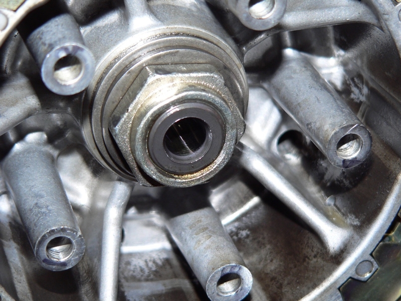
5. Remove the clutch hub nut and the two washers beneath it. Zip tie the three together so that they remain in the same order and with the faces oriented as they were when they were removed. Place these parts in a clean plastic bag.
Remove the clutch holder tools.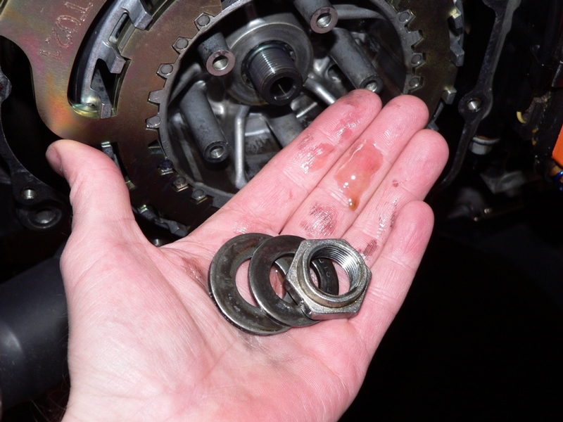
6. Use a Sharpie to mark the threads on the input shaft to two splines on the clutch hub. Pull the clutch hub straight out off of the shaft. Now mark the end of the spline on the input shaft.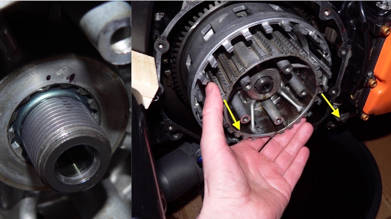
The anti judder ring and seat will be located around the bottom of the splines of the clutch hub. These parts do not need to be removed except for inspection or to replace them. Be careful not to let them fall off of the hub.
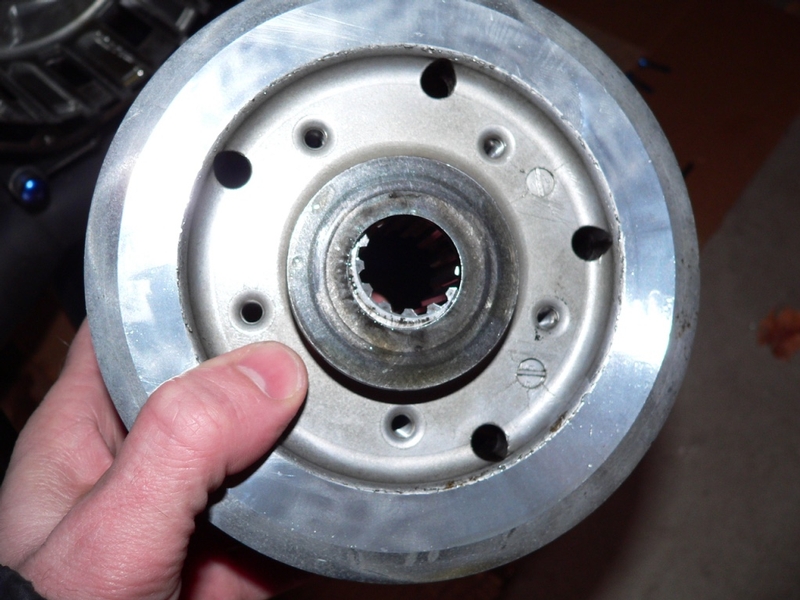
The inner flat washer will probably remain stuck to the hub on the other side. Be careful not to drop it and keep its orientation as removed.
Place the clutch hub, anti-judder rings and washer in a clean plastic bag.
7. Before pulling the sleeve located on the input shaft inserted through the center of the basket, mark the teeth of the big primary gear around the outside of the basket to the crankshaft gear. When the sleeve is removed, the clutch basket will be loose in the engine case and it will be impossible to positively match theses two gears together as they came apart. 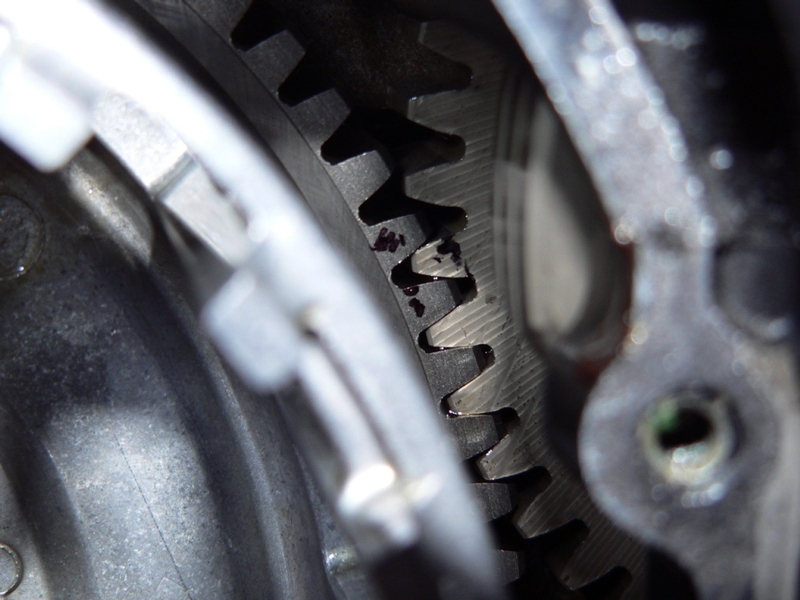
Use the spline you marked to the hub to mark the needle bearing sleeve in the same way. This is not vital because the sleeve does not have splines but may be helpful in reassembly.
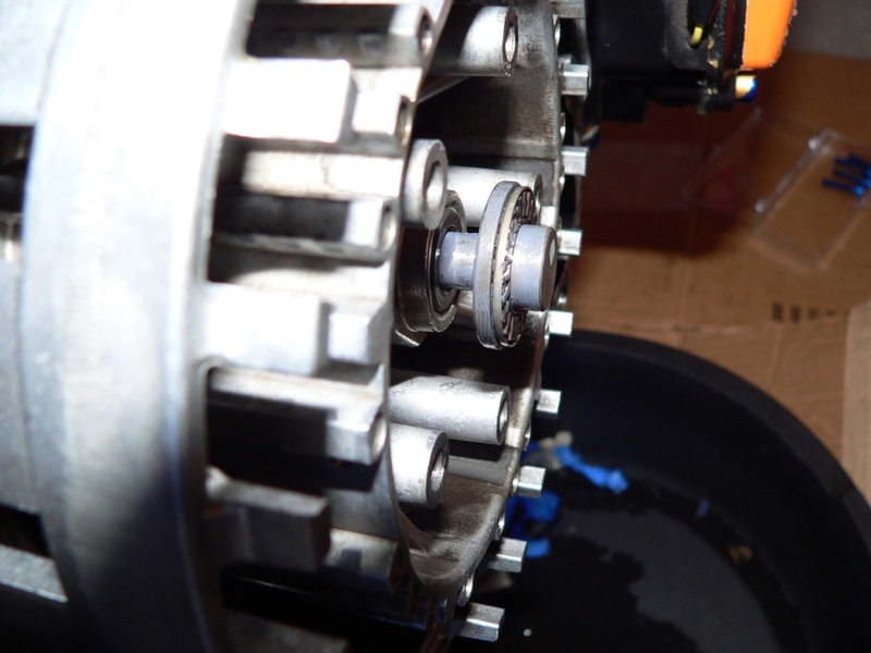
Thread an M4 x .7 x 25mm socket head cap screw into each of the two holes in the face of the clutch basket sleeve. Support the basket while you pull the sleeve straight out. The two sets of needle bearings will probably come out with the sleeve although they are not fastened together in any way. Be careful the needle bearings do not fall off of the sleeve or out of the basket after the sleeve is removed.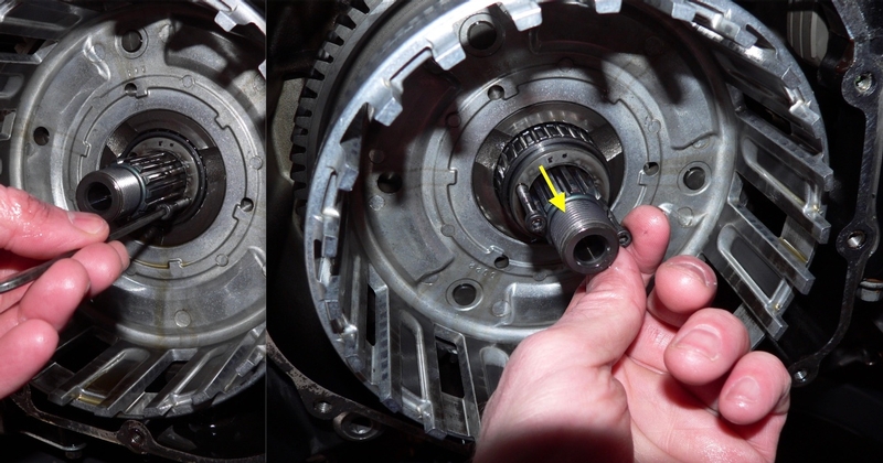
8. Move the clutch basket off center of the input shaft a half inch and pull it straight out of the engine case. The oil pump drive gear adjoins the back side of the the clutch basket. It will probably remain stuck by the short splines between it and the basket but be careful not to let it drop out if it does not stick.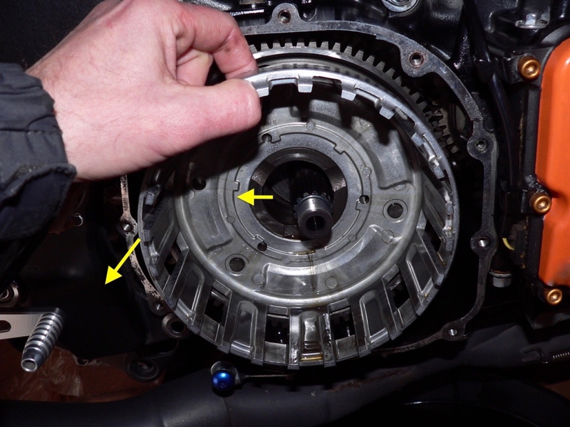
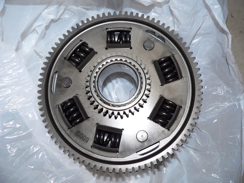
The oil pump drive gear is located on the LH side of the clutch basket. It’s not possible or important to mark the teeth of the drive gear to the oil pump gear with which it engages. The oil pump drive gear will probably remain stuck to the clutch basket if it is stored facing up but mark it’s splines to the splines on the clutch basket just in case it falls off.
The six springs on the LH side of the clutch basket help prevent chatter.
Place the clutch basket into a clean plastic bag with the oil pump drive gear facing up.
9. The Thrust washer will probably remain stuck to the crankcase wall. If you need to remove it, stick your fingernails under its edges and pull while turning to break the oil seal. Also, note that the chamfered side must face in toward the large bearing around the input shaft and the flat side faces out toward the clutch basket.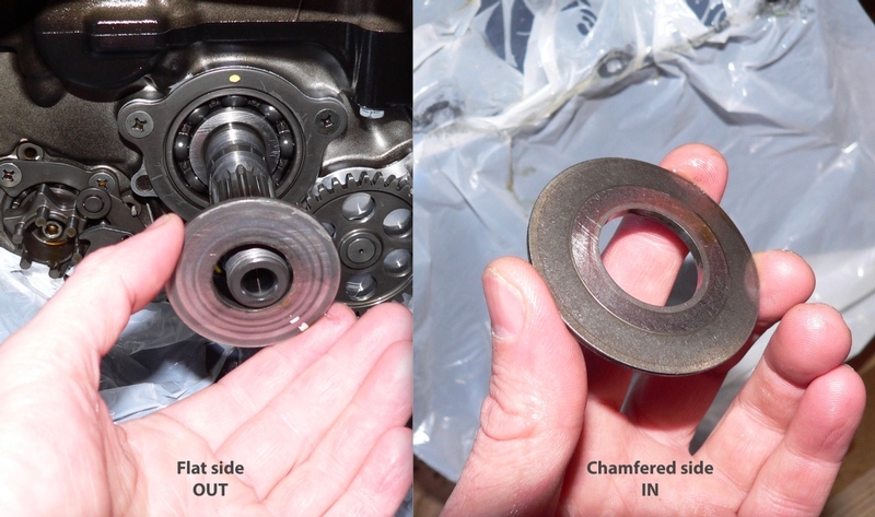
Installation
10. Verify that the inner thrust washer is installed to the input bearing as described in step 9.
Verify that the oil pump drive gear is installed to the clutch basket as described in step 8.
Place the clutch basket into the clutch case roughly aligning the marked teeth on the primary gear and the crankshaft gear. Allow the clutch basket to sit on the floor of the clutch case.
11. Apply fresh oil to the needle bearings and the sleeve. Slide the sleeve over the input shaft according to the marks you made in step 7.
Lift the clutch basket by hand. Engage the primary gear and crankshaft gear according to the marks you made in step 7.
Slide the needle bearings and sleeve through the center of the clutch basket. You may need to wiggle the basket a bit to slide the bearings through gently and smoothly. Do not force the bearings through the clutch basket.
Verify that the two 4 mm bolts have been removed from the sleeve.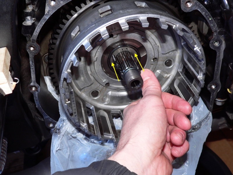
12. Place the inner flat washer onto the input shaft with the same side facing out as when removed. If this washer is still stuck to the back of the clutch hub, be sure it does not slide off before you get it onto the input shaft.
Verify that the spring seat is installed to the clutch hub along with the conical anti-judder spring. The anti-judder spring should be placed with the small diameter against the seat and the large diameter facing outward toward the clutch pack.
Slide the clutch hub onto the splines of the input shaft according to the marks you made in step 6. If you need to remove the hub to reposition the spline engagement, the inner flat washer may not remain stuck. Be careful that you do not drop it. 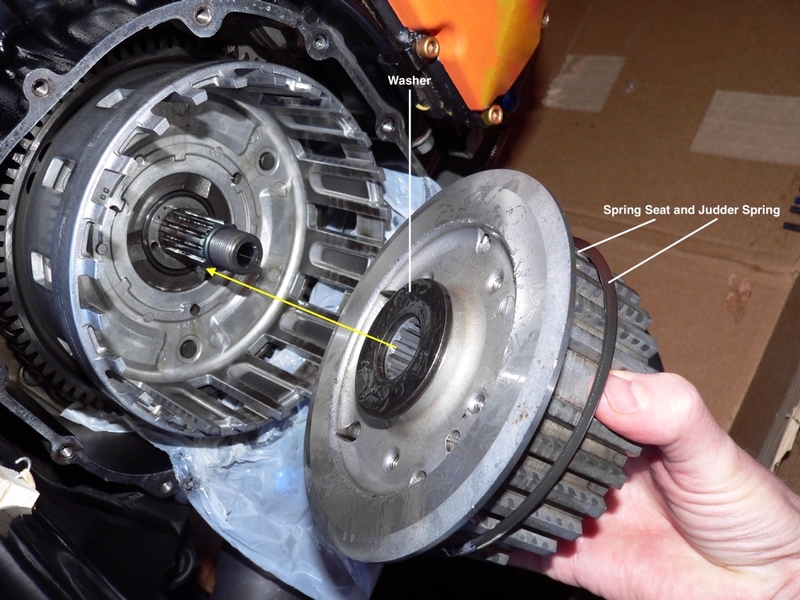
13. Place the outer flat washer with the same side facing out as when removed over the clutch hub nut threads on the input shaft.
Place the Bellview washer on the hub nut threads to the outside of the outer flat washer. The Belview washer has the words OUT SIDE stamped to its convex surface which must face outward as shown in the pic below.
The service manual torque spec is not for oiled threads. Clean and dry the threads on the input shaft with clean rags and mineral spirits.
Loosely thread the clutch hub nut (the service manual recommends using a new hub nut) onto the input shaft while holding the hub in position. The hub nut will turn the hub as soon as it gets finger tight.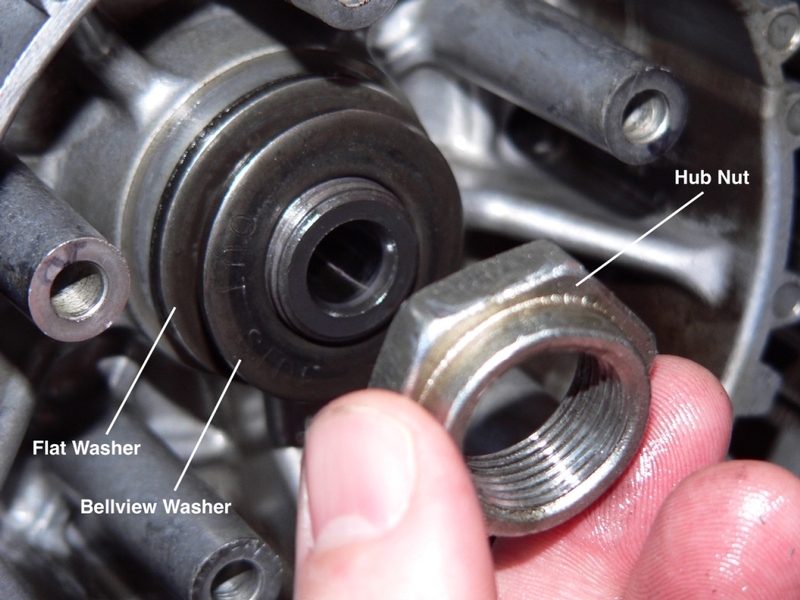
14. To tighten the clutch hub nut, you will need to hold the clutch holding tool handle down rather than up as you did to loosen it. Follow the directions in steps 2 and 3 to arrange the clutch holding tool. If you need to adjust the position of the clutch basket, use the clutch holding tool and only turn it counterclockwise as shown in step 3.
Use weights attached by a chain and hook or if you are using a swing arm pivot stand, you can use the spike to restrain the handle of the clutch holding tool. 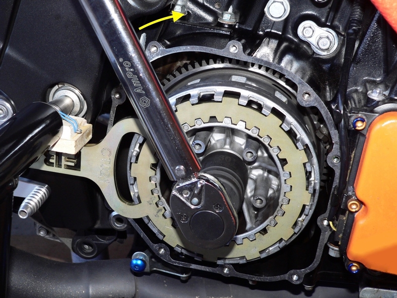
Use a 30 mm impact socket with a torque wrench to tighten the clutch hub nut.
Torque - Clutch Hub Nut: 135 Nm (13.8 Kgfm, 99.6 ft lb)
15. The service manual says, “apply molybdenum disulfide grease to the outside surface of the pusher.” This sounds like it means the portion that is outside of the input shaft or perhaps they mean the ends, only. I don’t see a problem with applying a light coat of molybdenum over the whole pusher. The oil will wash most of it off after a short time anyway and it won’t hurt the motor.
If you remove the thrust bearing from the tip of the the pusher, place it back on with the convex side of the stamped center ring facing out to the RH side.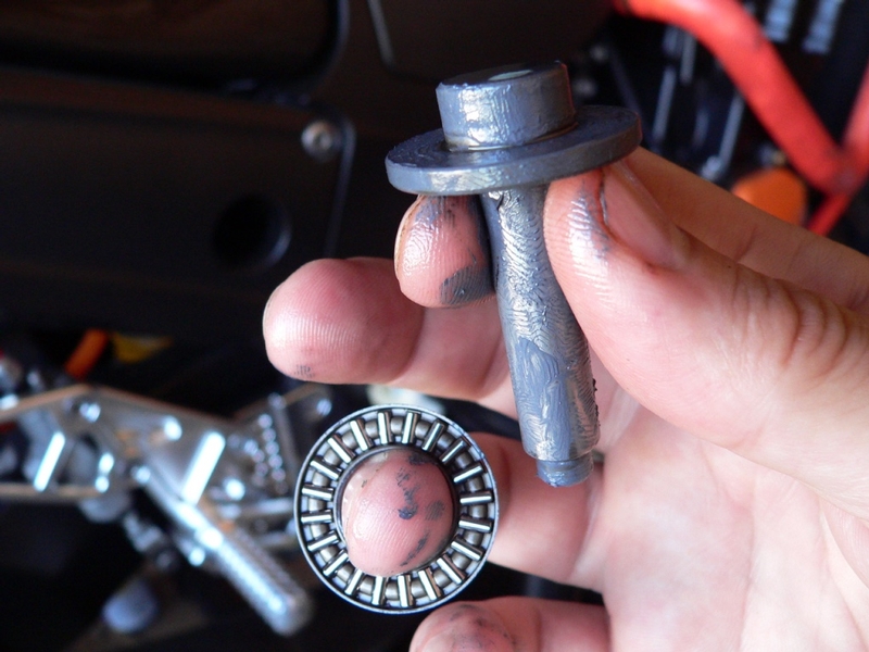
16. Insert the pusher to the end of the input shaft. You may need to push it in against the fluid pressure in the clutch slave cylinder which could have expanded while the clutch was disassembled. Keep an eye on the clutch fluid reservoir in case you need to remove some fluid to prevent an overspill.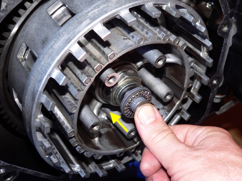
If the pusher sticks out about a half inch, that is normal. It will get pressed in when the spring plate is installed.
INSTALL CLUTCH PLATES, steps 7 through 13