


Throttle Bodies Sync, Gen1
The amount of vacuum produced by each cylinder will change as the engine wears. This will have an effect on intake and fueling requirements. Synchronizing engine vacuum ensures optimal flow is delivered to all cylinders.
If this is your first throttle bodies sync on the ZX-14, it will take some practice with the tools and procedures so don’t be in a rush. This procedure will probably take you all day (not including removing parts ) if you have never done it before. To avoid prolonged idling of the engine, you can shut it down while making adjustments and start it back up to check the adjustments. The special tools recommended to do the engine vacuum synchronization are a vacuum gauge sync tool, 90° angled screwdriver, and highly accurate tachometer.
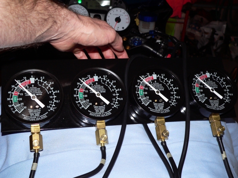
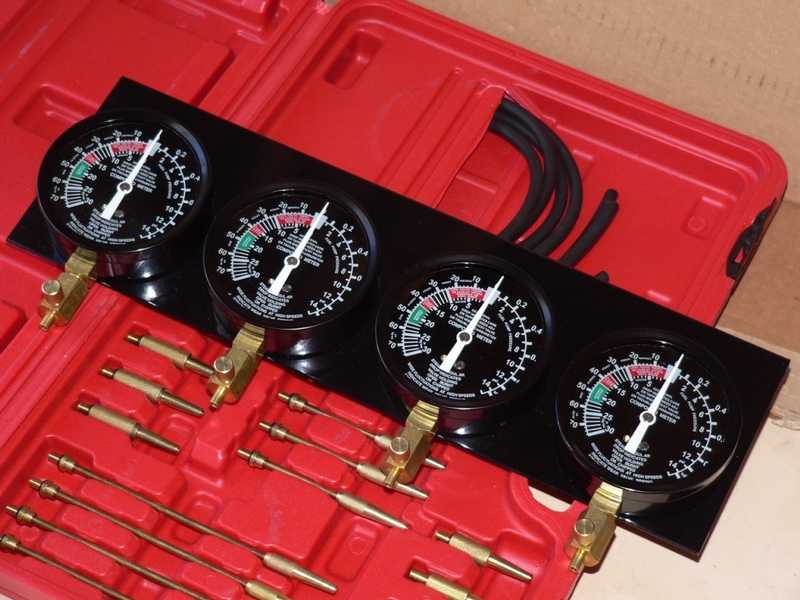
Vacuum Gauges or Manometer
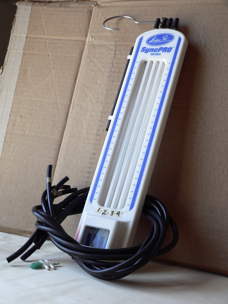
The 4 dial sync gauge tools available are going to be the best tool to use for measuring vacuum. They are easy to work with and are capable of measuring the value of vacuum being produced. Some fluid manometers such as the SyncPro do not measure vacuum quantitatively; they only compare the level of vacuum in each cylinder without expressing the vacuum on a numeric scale. Determining if the engine vacuum is in spec is only possible with a device that has an incremental display that shows vacuum measured in units of mmHg. The Sync-Pro manometer seems to be the the most common syncing tool in use but it provides less information and actually costs more than most of the common vacuum gauge sync tools. The SyncPro is problematic to use because the fluid sticks in the columns which renders it useless until the fluid is cleared.
How To Use the Motion Pro SyncPro Carburetor Tuner v the ABN Carb and Throttle Bodies Sync Gauges
Read this thread for some great tips on tool choice and one great technique that will make this job a lot easier.Throttle body sync tip
90° Angled Screwdriver
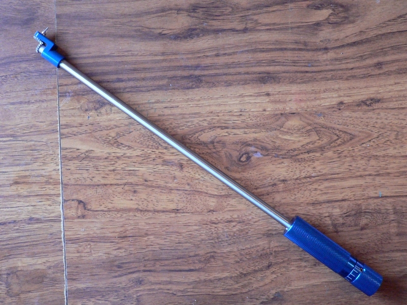
I did quite a lot of internet research on pilot screwdrivers and determined the best one for the 14 is the Motion Pro 90° carb tool. It lacks the sleeved neck that is designed to fit over protruding adjuster ports or screw heads but the sleeve also requires more space. Extra space is something you DO NOT have when tuning the throttle bodies on the ZX-14. The Motion Pro 90° screwdriver is going to cost you a lot more than some of the pilot screwdrivers but I believe it’s the only one that will be useful for the ZX-14. The click stops in the handle are not of much use on the ZX-14 throttle bodies because it is not always easy to tell if the bit is set in the screw slots or if it has slipped out. The bits that come with the Motion Pro 90° screwdriver are too small for the 14. With some replacement bits, the Motion Pro 90° screwdriver works as easy as can be expected. More than anything, practice is required to use this tool effectively. These problems are dealt with later in the tutorial.
Tachometer
You must have the engine idle speed at exactly at 1100 rpm to compare the vacuum produced in the throttle bodies to the specced vacuum range but it’s possible to balance vacuums at any rpm. The bike’s tachometer is adequate but it may be less precise than a diagnostic tachometer or real time data display such as Dyno Jet”s LCD-200 or POD-300. At $300-$500, you may wish to forgo a good diagnostic tool with tachometer and several other functions in favor of the bike’s OEM tachometer. On the other hand, a multifunction diagnostic tool will probably be able to measure voltage which is the final step of syncing the throttle bodies.
HOW THE THROTTLE BODIES ADJUSTMENTS WORK
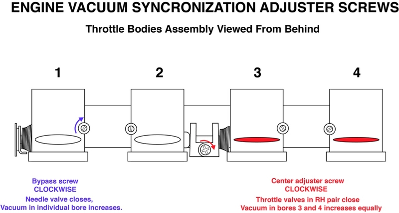
Center Adjuster Screw
There are two kinds of adjustments to make when syncing throttle bodies. The first is adjusting the angle of the throttle plates. Opening the throttle plates will increase flow of air which will reduce the vacuum in the throttle bodies. Closing the throttle plates has the opposite effect.
The throttle bodies actuator arm is divided into two halves that are joined at the center. The split arm design allows the angle of one half to be adjusted independently of the other half. The angle of the throttle plates is adjusted by turning the center adjuster screw which is located on the actuator arm. The center adjuster screw is accessed from the back of the throttle body assembly directly between bores #2 and #3. The center adjuster screw is difficult to see even with a mirror. It is not possible to view the center adjuster screw without a mirror.
By turning the center screw clockwise, the plates to the RH pair (cylinders #3 and #4) close a small amount. This reduces the flow of air thereby increasing vacuum in both throttle bodies #3 and #4. Turning the center adjuster screw counterclockwise opens throttle plates #3 and #4 which reduces vacuum in those throttle bodies. Turning the center adjuster screw seemed to only effect the RH pair (#3 and #4). The LH pair was not effected by the adjustment of the center adjuster screw regardless of how far I turned it. I was able to turn it about one quarter of a turn either way and I do not believe it would turn much more than that. It seemed to reach a point where the screw bumped against a stop when turning it full counterclockwise and still, the vacuum in the LH pair (#1and #2) was not effected. If it was necessary to change vacuum to the LH pair via throttle plates, I suppose you could adjust the idle (effecting all the throttle plates equally) and then the RH throttle plates with the center adjuster screw.
There is a coil spring which maintains tension between each half of the actuator arm. Additionally, the center adjuster screw is equipped with a stiff tensioner spring under its head that prevents the screw from vibrating out of adjustment. For these reasons, the center adjuster screw does not turn with ease. Fortunately, it is not necessary to turn it very much to produce the desired effect.
Do not be afraid of adjusting your throttle plates angle out of whack. The change is very small. It is probably barely noticeable on visible inspection if at all. You can’t change it much and you would not need to. There is no telling if the throttle plates came from the factory at exactly 0° and how the plates were adjusted from the factory does not matter if the vacuums are now out of sync. Set the plates so that the engine runs at its best right now. You can’t overdo this so go ahead and adjust the throttle plates as needed.
Bypass Screws
Usually, all of the throttle body vacuums are different before making the first adjustment with the center adjuster screw. For this reason, you will probably not be able to bring all throttle bodies to the same vacuum by using the center adjuster screw alone. You will only balance the highest vacuum on the LH pair to the highest vacuum of the RH pair by turning the center adjuster. The bypass valve adjusters are located in cylindrical protrusions at the back of the throttle bodies. The screw inside of the protrusion is threaded in to close the valve or threaded out to open the valve.
The lower vacuums of each pair are adjusted by the bypass valves. Each of the four bypass valves effects vacuum to an individual throttle body in the same way that the throttle plates effect vacuum to the LH pair. The bypass valves are small needle valves that control the amount of airflow from passages that supply extra air. If a bypass valve is opened, it increases the air available which reduces vacuum in that individual throttle body only. So, close the bypass valves of the throttle bodies that have lower vacuum until they reach the same level as the high vacuums that were balanced with the center adjuster screw.
The bypass screws are pretty easy to turn (provided you can get the screwdriver bit in them squarely). If you turn a bypass screw in until it stops, STOP! The needle valves are delicate and can be damaged from over-tightening. Damaged needle valves disrupt flow and they are very labor intensive to replace. If you are threading a bypass screw out and you do not see the vacuum reducing in that throttle body, STOP!, The needle valve is already all the way open. Opening it more will not increase airflow. This is probably a built in safeguard against having a screw accidentally fall out or vibrate out during adjustment or operation. There are tension springs under the bypass screws and they will not work if they are not under tension. Except for removing them, there is no reason to turn the screws past full open.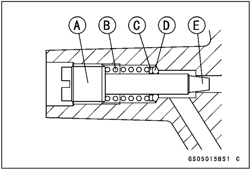
(A) Bypass Screw head
(B) Tension spring
(C) Washer
(D) O-ring
(E) Needle
Theoretically that is how a sync works but in reality it is usually a bit more complicated. Any time you adjust one screw, it seems to have some impact on the vacuum of the other throttle bodies. My sync was a process of bouncing back and forth between all 5 screws zeroing in until I got it right. End result was that all four vacuums were nearly perfectly equal. If your bike is newer, it will probably require a lot less readjusting before you get it right. If your throttle bodies are only slightly out of balance, you may be able to balance them by using the bypass screws only.
Syncing my throttle bodies to a dangerously lean AFR was a concern I had but upon further consideration, this seems impossible to do. If the exact vacuum can be determined with a vacuum gauge and the throttle bodies have vacuum that is in spec, lean AFR can not be a danger. If there is too much air coming in that would be the same as opening the throttle, the ECU would adjust fueling accordingly and the idle would increase which you would just adjust back down with idle adjuster knob. I don’t see that dangerous AFR is something to worry about when syncing.
There are different approaches to synchronizing engine vacuum. Except where otherwise noted, the process this tutorial explains is identical to the process described in the ZX-14 service manual. It will be up to individual throttle body tuners how they wish to vary from this procedure. I think this tutorial details a good approach for the person doing this for the first time and will provide a good background to develop individual tuning methods in the future.
It’s important to mention that the throttle bodies vacuum sync I performed on my bike which was way overdue produced no noticeable change in idle or performance. It is my opinion that unless your engine is running poorly, there is probably no reason to expect a lot better performance after a vacuum sync.
Here are some previous threads about throttle bodies syncing.
Tools:
telescoping magnet tool
telescoping mirror tool
penlight
needle nose pliers
nail clippers
15” x 5/16” wide battery ground strap
golf tees
tape
vacuum gauges
micro screwdriver
2" phillips bit
Motion Pro 90° carb tool
1" small straight slot bit
DO FIRST:
*Lift the bike on a rear stand in a clean environment free of airborne dust and dirt.
*Remove fairings (see Fairings Removal, Lowers, Foremans, Ram Air Covers, Fuel Tank Cover, Inner Upper Fairing and Side Fairings).
*Pull the air switching valve hose from the grommet. Block the hose and the grommet (see PAIR Block Mod, full procedure). Pull off vacuum hoses for CAL models.
*At this point, I highly recommend taking a dry run at steps 1 through 3 of this tutorial. Remove the test fitting caps, have a look at the adjuster screws and determine if you want to go through with a sync or do you just want to test vacuum for now... or do you want to just forget about it. The tools cost money, the space is very limited and the screws and fittings are not easy to reach.
*Did you decide to go through with it? Good. Read on.
Fittings and Adjuster Screws
1. The test fittings are located to the front of the throttle bodies. Compress the wire spring retainer on the rubber test fitting caps. Pull the cap off of the test fitting.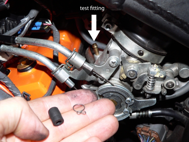
If you first twist the cap and wiggle it while pulling up, the cap should come off without removing the spring. A telescoping magnet tool will help to retrieve the cap and / or spring from your fingers inside the engine compartment. OK, that was the hardest part. You now know where the test fitting caps are and now you will be able to remove them pretty quickly for the test. Place the caps back on.
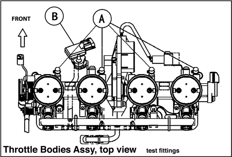
The test fittings are labeled [A] in the above diagram. Number 2 test fitting is very hard to reach but the inlet air pressure sensor connector leads labeled (B) above fitting number 2 are secured by a flexible rubber attachment. This helps to bend the connectors out of the way to reach over and around them with the palm of your hand.
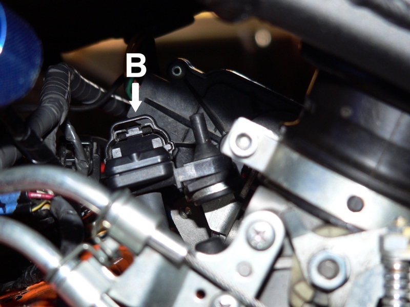
It may also be helpful to separate connectors (B) but be sure to connect them back up before starting the engine. I turned the key on with these connectors separated and the fan came on. I did not try to start the engine with them separated.
2. Use a telescoping mirror tool and penlight to locate the center adjusting screw (B) between the backs of throttle bodies 2 and 3. 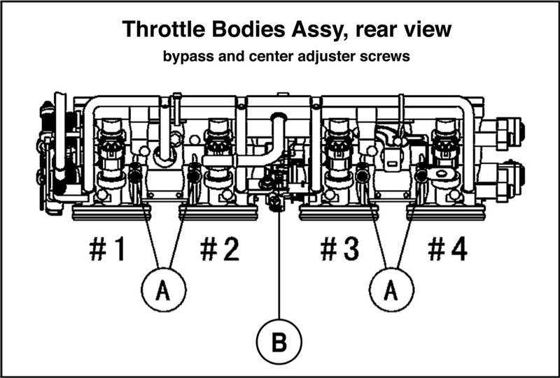
(A) bypass screws. (B) center adjuster screw.
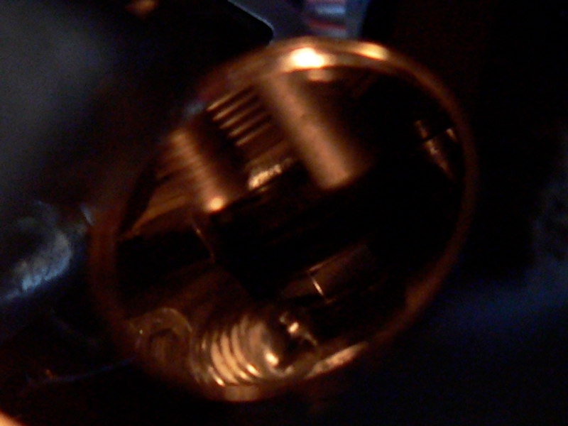
Viewed from the LH side and with the mirror situated below, this picture shows an image of the center adjuster screw which is a phillips/straight slot combination. You see a winding of actuator spring which is located next to the center screw. Also note the tension spring behind the head of the center screw.
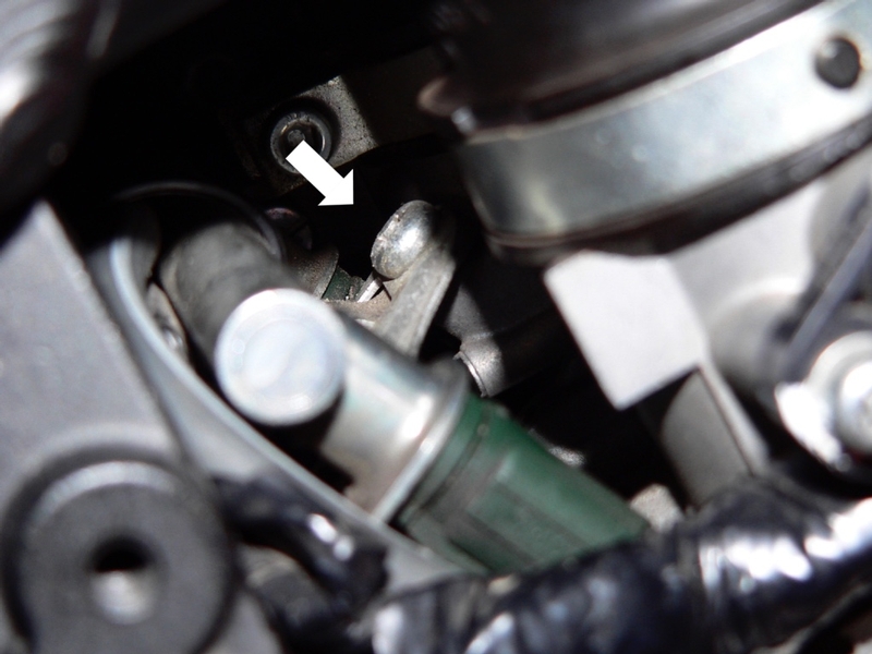
Locate the bypass screws (A) at the back of each throttle body.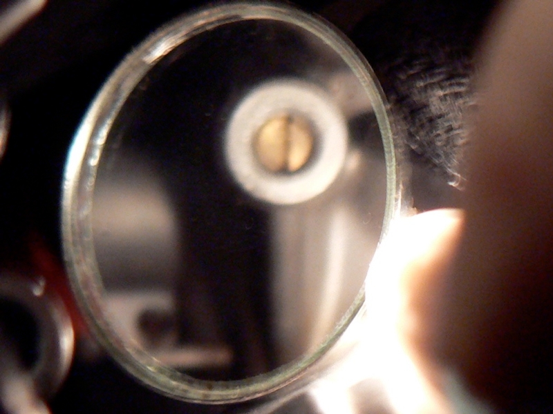
This picture shows the mirror reflection of a bypass adjuster screw viewed from directly behind. Note they are straight slot screws seated in tubular protrusions coming off of the throttle bodies.
Accessing Bypass Screws
By now you have probably realized that there is a problem with accessing the bypass screws on the RH side. You will need to take the following steps.
First, the crankshaft sensor wire connectors are in the way.
3. Remove the crankshaft sensor couplers from their bracket by compressing the pawls with a needle nose pliers and pulling the the catch through the hole in the bracket.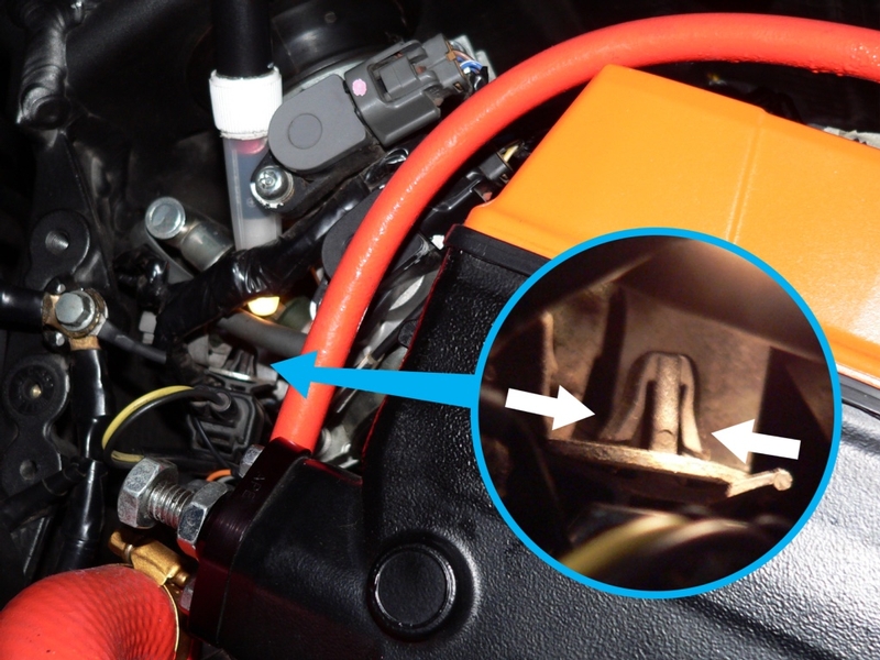
Leave the connectors together but clear them near the thermostat below and behind the main water hose on the RH side.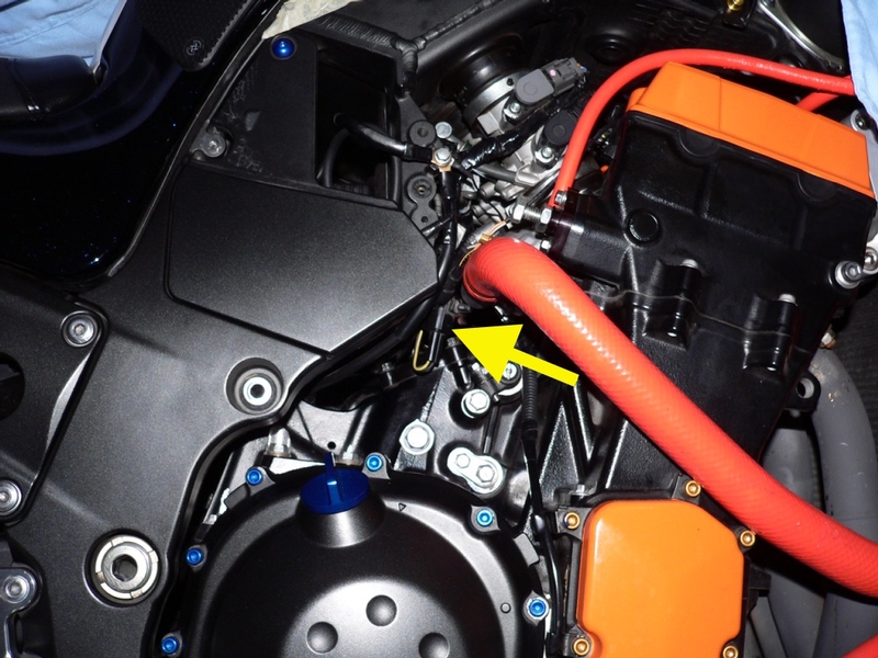
The bracket (B] for the crankshaft sensor wire couplers crosses directly in front of the bypass screw for throttle body #4 [#4] and the throttle bodies wiring harness (bundle of black taped wires) is zip tied [Z] to the bracket obstructing the path to both bypass screws #3 and #4.
There is still no way you will get an angled screwdriver on bypass screws #3 and#4 squarely unless the the bracket is moved out of the way.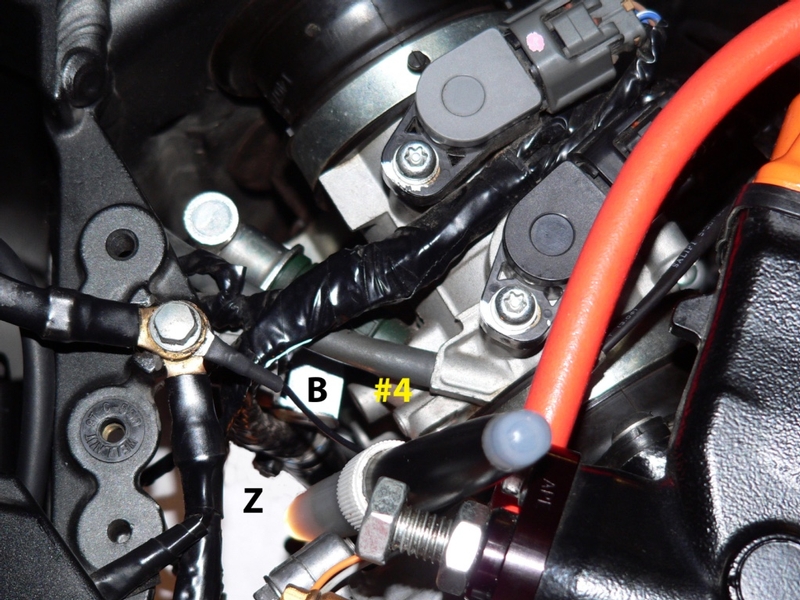
There is a button head phillips screw that secures the bracket to the throttle bodies. I was not able to remove it after considerable effort so bending the bracket clear seems the only practical alternative.
4. Grabbing the tab of the bracket with a needle nose pliers, bend the bracket outward while pressing from behind with a finger. Bend just enough so there will be room to get the bit on the bypass screw. You do not need to bend it much. Be careful that the bracket tab clears the grey connector to fuel injector #4.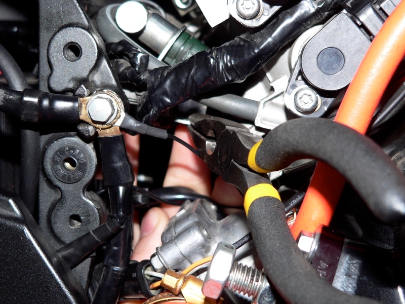
At this point, you may be able to get the °90 screw driver onto bypass screw #4 but the throttle bodies wiring harness runs diagonally from the upper RH side of the throttle bodies to the lower LH side. This will make getting the screwdriver on bypass screw #3 and #2 difficult.
5. Use a pair of nail clippers to cut the catch on the zip tie that retains the throttle bodies wiring harness. DO NOT cut to the bottom of the catch near the wires. Carefully nip the top off of the catch about halfway down its height and this will be enough to cut off the tiny plastic pawl that locks it.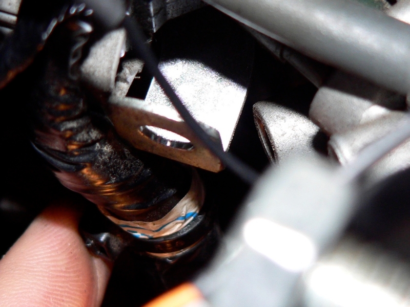
I was able to twist the zip tie counter clockwise with my fingers so the catch is in view. You also see the bracket and bypass screw #4.
6. The final step to freeing up the throttle bodies wiring harness is to remove the throttle bodies subharness main connectors from the bracket on the engine (see Throttle Bodies Assy Removal, Step 3).
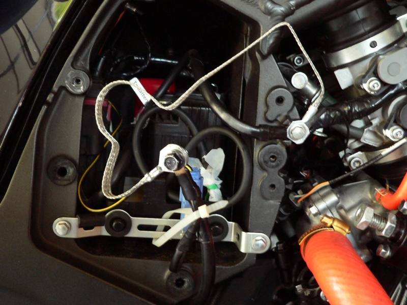
The throttle bodies wiring harness is now loose enough to push aside in order to reach all of the bypass screws with a 90° screwdriver. It will probably still not be possible to get a 90° screwdriver on screws #3 and #4 without removing the ground wires from the lower RH corner of the outside of the battery box on the RH side of the bike. You will need to have these wires grounded in order to do the sync so a jumper wire will be required to make the ground connection while temporarily moving the wires out of the way. I used a 15” x 5/16” wide battery ground strap of braided steel strands. If you decide to make up your own jumper wire, be absolutely certain it is the proper gauge wire to safely conduct the amperage of starting and running the engine. If it is too small, it will smoke melt or catch fire.
7. Remove the ground wires from the RH side of the battery box (see Battery Removal, step 3)
Using a bolt, two steel washers and a nut, connect a suitable jumper to the ground wires that are obstructing access to the bypass screws. Using the OEM ground screw, connect the battery ground and the other end of the jumper to the ground on the battery box.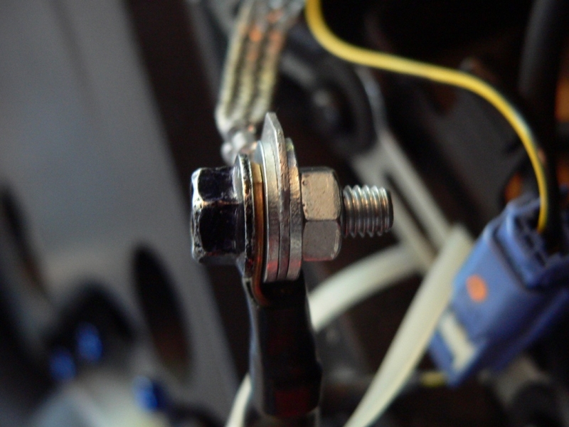
Sync Tool Calibration
DO NOT RUN THE ENGINE WITHOUT HAVING ALL TEST FITTINGS ON THE THROTTLE BODIES BLOCKED FROM THE EXTERNAL ATMOSPHERE.
Since the ZX-14’s throttle bodies test fittings are so hard to reach, I found it best to attach the hoses before warming the engine for the test. You can warm the engine first but it will burn your hands when you remove the test fitting caps and attach the hoses. The engine also will probably have cooled off by the time you have all the hoses attached.
8. Remove all test fitting caps from the throttle bodies and attach the vacuum hoses to the test fittings. The hollow bottoms of the restrictors goes in the hoses toward the test fittings if you are using the SyncPro. Use golf tees or tape to block the open ends of the hoses. Do not leave the ends of the vacuum hoses hanging open while running the motor. 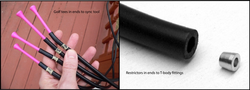
You should also tape over the tank fairing grommets since the holes lead directly into the air box.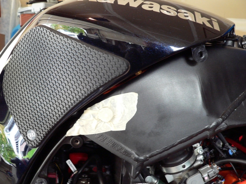
9. Make sure the throttle bodies test fittings are not open and that the electrical leads (see step 1 of this tutorial) are connected. Connect your highly accurate tachometer (if you are using that instead of the bike’s tach). Start the engine and warm it up thoroughly. Use the throttle adjuster nob to set the idle at 1100 rpm.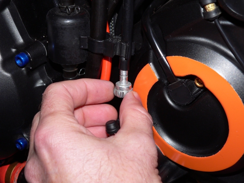
Running the idle lower than 1100 rpm will increase vacuum; running the idle higher will decrease vacuum. It is possible to synchronize the vacuums at any rpm. In fact, with a higher vacuum across all throttle bodies at low rpm, you should be able to balance them more precisely. You would need to adjust the idle back up to 1100 to check if the vacuum is in spec. Idling the engine at extremely low rpm is not recommended because it is hard on the crankshaft.
10. After the engine has warmed up and had the idle adjusted to 1100 rpm, you may calibrate the vacuum gauges (see How to Use the SyncPro v the ABN Vacuum Gauge Sync Tool) while the engine is running.
Synchronizing Engine Vacuum
11. Attach vacuum hoses to the sync tool inlets in the same order as the hoses are connected to the throttle bodies, 1, 2, 3, 4 from left to right. It’s a good idea to label each hose and each gauge with a numbered piece of tape to avoid confusion. 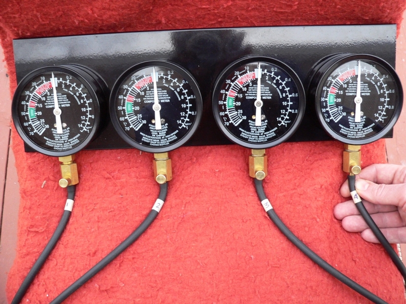
12. Start the motor and allow it to run until it reaches normal idle speed of 1100 rpm. Record the present vacuum levels indicated by the vacuum gauges for each cylinder. Use pieces of tape to mark the height of the fluid columns if you are using a manometer.
The first goal is to equalize the highest vacuum of cylinders #1 and #2 to the highest vacuum of cylinders #3 and #4. We are not concerned about what happens to the lowest vacuums right now.
Here is an example of vacuum levels measured before any adjustments:
Cyl #1 250 mmHg
Cyl #2 270 mmHg
Cyl #3 250 mmHg
Cyl #4 260 mmHg
The highest vacuum of the LH pair is 270 mmHg. The highest vacuum of the RH pair is 260 mmHg. We want to adjust the vacuum between the pairs until #3 is the same vacuum as #2.
Turning the center adjuster screw clockwise will compensate for a weaker high vacuum in the RH pair. Turning the center adjuster screw the counterclockwise would compensate for a weaker high vacuum on the LH bank.
13. Place a small 2" phillips bit in your Motion Pro 90° carb tool.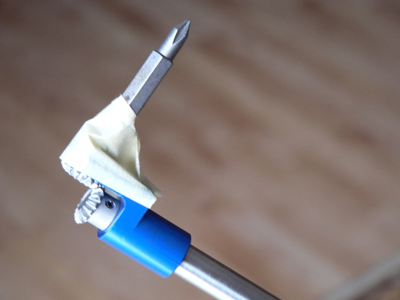
The center adjuster screw head has combination straight slot/phillips slots and the phillips will give the most secure bite. The standard #2 phillips bits for drills are probably too large to fit the center adjuster screw securely. The phillips bit that comes with the Motion Pro is much too short to reach the center adjuster screw on the ZX-14. The bit I used was from an interchangeable bit screwdriver set. The bit does not have a spring locking ball so I loosely wrapped a sheath of masking tape around the shank of the bit and the tip of the tool. The bit did not fall out but I was also careful not to point the bit downward while working. You may want to paint the bit so it’s easy to see should it fall out.
14. Before proceeding, you might want to look at the places a bit may fall into if it does drop out of the 90° screwdriver. As a precaution, cover any of these areas up with something that won’t melt or catch fire.
Also, you will probably want to turn the engine off to do this first adjustment if this is your first sync. It’s aggravating enough without having the motor running.
Place a telescoping mirror tool directly below the center adjuster screw. Place the penlight as near as possible to the center adjuster screw without obscuring the mirror view of it. I used the throttle bodies harness connectors bracket as a place to clip my penlight directing the bulb at the center adjuster screw. Tape the handle of the mirror tool to the main wiring harness to steady it so the center screw can be viewed. Reach in with the 90° screwdriver from the LH side of the bike. Insert the phillips bit in the center adjuster screw.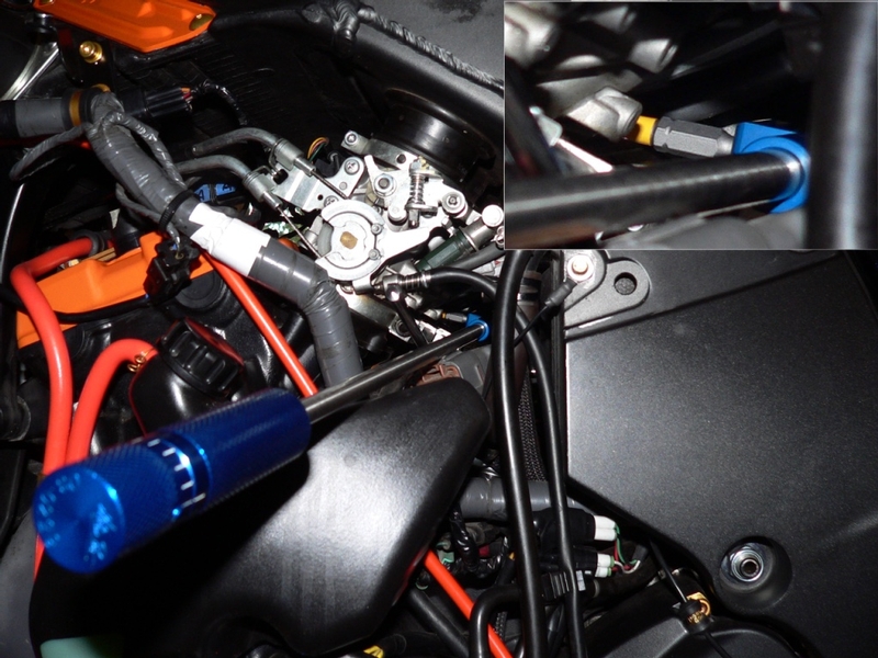
90° screwdriver use pointers:
Note the orientation of the x slots in the center adjuster screw before turning it so you can visually check if it turned or not. Chances are you will not need to turn the center adjuster screw much more than 1/8 turn but you can forget about counting click stops of the 90° screwdriver handle. The bit is going to slip, you will not know if the handle click stopped dropping into the slots or if it was the screw turning. Just because you feel a click, that does not mean the screw turned, the drive mechanism of the screwdriver may have flexed (that screw is tight)….but you will feel the screw turn through the tool. Personally, I wish Motion Pro didn’t have the click stops in the handle.
The throttle bodies are mounted tilted backward but the center adjuster screw is oriented parallel to the ground rather than perpendicular to the vertical axis of the throttle bodies. To seat the bit square in the slots, insert it level to the ground (see the inset photo above). Turn the nob on the handle of the 90° screwdriver until you feel the bit drop into the X slots.
The throttle bodies are mounted tilted backward but the center adjuster screw is oriented parallel to the ground rather than perpendicular to the vertical axis of the throttle bodies. To seat the bit square in the slots, insert it level to the ground (see the inset photo above). Turn the nob on the handle of the 90° screwdriver until you feel the bit drop into the X slots.
The center adjuster screw has a tension spring to prevent engine vibration from moving it. You will need to press the bit very firmly into the screw slots to prevent the bit from slipping. You will probably feel the actuator arm turn opening the throttle plates if you are pressing hard enough. If the bike is running, the engine speed will spin up immediately to about 4000 rpm so be ready for that.
While pressing the bit into the screw slots, twist the 90° screwdriver nob clockwise to turn the screw clockwise or twist counterclockwise to turn the screw counterclockwise. You should review this thoroughly beforehand. Don’t be confused by pointing the tip of the bit at you to view its rotation. Clockwise/counterclockwise rotation of the bit is viewed with the bit pointing away from you just as it would if the bit was set in a screw—-otherwise it’ll be opposite like looking in a mirror)
I think that’s all I can tell ya. You just have to try it out. Trust me, if you’re patient, you get the hang of it. You’ll be adjusting with the engine running once you get the feel. I sure think Kaw could have given us an allen screw instead of that damned phillips though. Maybe I will see if I can change in an allen head next time I remove throttle bodies.
15. After each adjustment of the center adjuster screw, open and close the throttle quickly to seat the throttle plates (this often happens automatically if you press the bit hard enough against the screw slots). Adjust idle speed if necessary. View the difference your adjustment made in the values of vacuum measured by the sync tool. If you need further adjustments to balance the highest vacuums between the pairs, repeat step 15. Try fine tuning with the engine on to this time.
16. After the higher vacuum of cylinders #1 and #2 is balanced to the higher vacuum of cylinders #3 and #4, use the bypass screws to adjust any of the 4 throttle bodies that has a vacuum that is out of specced range.
Throttle Body Vacuum?
Standard: 34.4 ±1.3 kPa (258 ±10 mmHg) at idle speed
To continue the hypothetical throttle body sync from step 13, the vacuums might look like the following after the highest vacuums between the pairs have been balanced by adjusting the center adjuster screw:
Cyl #1 250mmHg
Cyl #2 270 mmHg
Cyl #3 255 mmHg
Cyl #4 270 mmHg
The bypass screws of throttle bodies #1 and #3 need to be adjusted to bring their vacuums into the specced range of 258 mmHg ~ 268 mmHg. All vacuums should be adjusted so that they are equal and in spec.
Change the bit in the 90° screwdriver to a 1" small straight slot bit and sheath it loosely with masking tape as suggested for the phillips bit in step 14 of this tutorial. 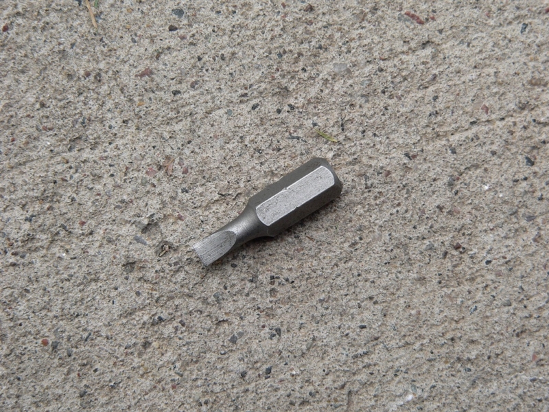
Pointers for adjusting bypass screws:
To increase vacuum to an individual throttle body, turn its bypass screw clockwise. To lower vacuum to an individual throttle body, turn its bypass screw counterclockwise.
Bypass screws do not change the vacuum as drastically as the center adjuster screw. Chances are you will be turning the bypass screws several turns.
The bypass screws turn very easily compared to the center adjuster screw. Be careful of threading the bypass screws all the way out and dropping them. Also, make sure there are at least a couple threads at the beginning of the screw hole visible or the screws may vibrate out. There are tension springs under the bypass screw heads to prevent engine vibration from turning them. The farther the bypass screws are adjusted out, the less tension the springs exert on the screw heads.
Don’t apply any kind of thread locking agent to bypass screws.
Be careful not to thread the bypass screws in farther than the point where they stop. If you tighten them, the delicate needle tip may deform and disrupt flow.
Adjusting a bypass screw may have an impact on the vacuum measured on the other throttle bodies as well as the one you are adjusting. You may find it best to go back to the center adjuster screw to finish equalizing all four vacuums.
* Last updated by: Rook on 12/29/2017 @ 3:57 PM *