


Modifying an Oil Sending Unit Adapter for the Oil Switch Boss
The thread pitch for the oil switch boss is 1/8” NPT which is the most common thread used for automotive sensors. It will be easy to find a 1/8” NPT adapter that will accommodate one or more sending units for aftermarket gauges and the stock oil pressure switch all in one. The problem is that the oil pressure switch boss hole’s tapered threads are cut smaller than the standard range of 1/8” NPT thread diameter. It will not be possible to fit an adapter or most other 1/8” NPT fittings into it unless the fitting is modified. 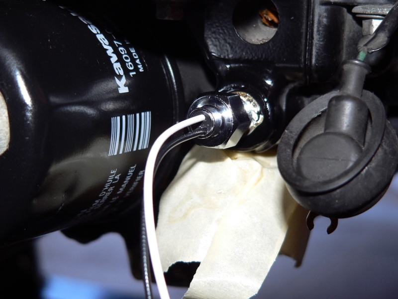
My oil temperature sensor threaded into the switch boss easily. Its 1/8” NPT thread diameter was made extra small so that the sensor’s probe extends deep into a standard sized port. A standard sized 1/8” NPT fitting will not go in the oil switch boss.
First, let’s consider which adapter to purchase. The male threads on the adapter must be tapered 1/8” pipe threads, either NPT or BSPT. There must be enough ports in the adapter to accommodate the sending unit(s) and the stock switch. The adapter must be strong enough to withstand vibration.
Brass
A brass fitting is not desirable for supporting the weight of an adapter and multiple sensors which often extend a couple inches away from the fitting. Threads are inherently weak because of their corrugated structure and brass is more prone to breaking because it is so soft. An inexpensive brass 1/8” NPT cross adapter and male/male nipple will supply oil temperature and oil pressure sending units as well as the oil pressure switch. However, that amount of weight cantilevered a few inches from the motor could cause a crack in the nipple resulting in rapid and complete oil loss. The fact that the male threads that go to the boss require reduction disqualify brass as even an option for temporary use. The inner diameter of a brass fitting is usually 7/32” or more while adapters with male ports molded in as one piece typically have a 1/8” inner diameter. The large inner diameter of fittings already decreases the thickness of the pipe wall and it will be necessary to reduce it more to get it to fit the boss. Tightening it would be a cracking hazard let alone, the vibration and shock of operating the bike on the road. Another disadvantage of the brass cross fitting is that one sensor will need to be positioned pointing downward which would make the adapter and sensor more prone to damage from road debris hitting it. Don’t bother trying brass for this application.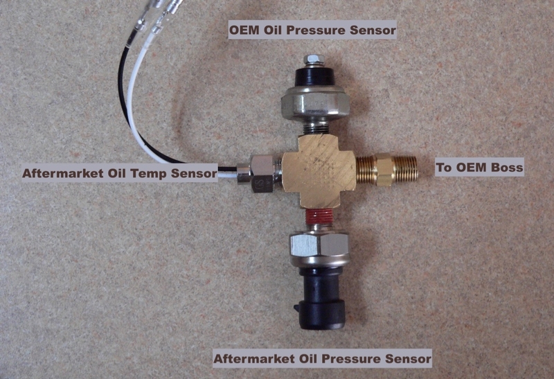
Aluminum
I was hoping to find an aluminum distribution block or 4 port fitting that would work in place of a heavy brass fitting. After looking high and low, there was nothing in aluminum on the entire internet that seemed as though it would both fit and be safe. Aluminum is lightweight and its strength is superior to brass but most aluminum is still is not the best choice for resisting vibration and sudden jarring. Some distribution blocks are bulky and there is not much space to spare where the adapter must be installed. Distribution blocks are designed to accommodate hose fittings which are smaller than sensors. The female ports on distribution blocks are drilled too close together for typical oil sensors. The stock oil pressure switch is about an inch wide across opposite points on the flats and an aftermarket sensor will be close to that size. It seems likely that two sensors placed in neighboring holes in a distribution block might not fit next to one another.
If a six hole aluminum distribution block such as the one shown below were used with an inlet port consisting of a stainless steel male/male fitting, it might be reliable. To accommodate three sensors, this distribution block would require that two sensors be placed one hole apart with the empty port between them being plugged. One sensor would need to be positioned so that it points downward presenting the hazard of damage from flying road debris. The male/male fitting would need to have a 1/8” inner diameter to permit the threads to be reduced without sacrificing too much thickness of the fitting’s wall. As mentioned before, fittings often have an inside diameter that is a lot larger than 1/8” so reducing their outer diameter is problematic. This distribution block would be supporting about a quarter pound of weight on a two and a half inch lever so if I used it, I would only use it with a stainless steel fitting with a small inside diameter.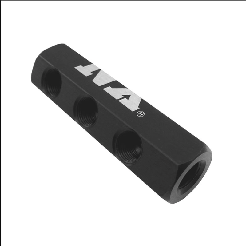
Stainless Steel
Stainless Steel oil pressure sensor adapters are heavy but the big advantage they have in strength make them the best choice for an oil sending unit adapter. The usual problem of the male port not fitting the oil switch boss will still be a factor but here, we also have an advantage. The male port on a stainless steel adapter will be molded into the piece and it will have a 1/8” inner diameter. This will give you the pipe wall thickness required to reduce the thread diameter. Stainless steel oil sending unit adapters are available with two or three female ports. You might be able to make additional ports but stainless steel is difficult to drill and thread because it is so hard.
Unfortunately, these adapters are designed with a combination of holes having two different thread pitches so that a stock hole can be adapted for use with the stock sensor and sensors of some other pitch. The ZX-14’s stock sensor has 1/8 NPT threads and that is also the thread pitch you will need for most aftermarket sensors. This tutorial will show you how to convert an adapter to 1/8” NPT threads in all ports.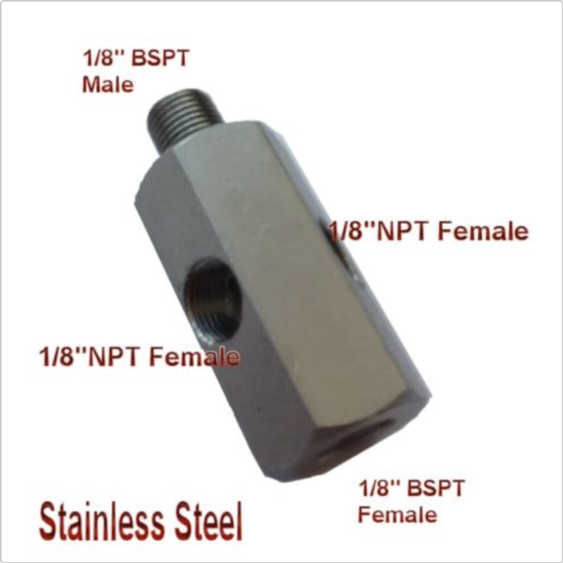
I have never used a hexagonal adapter such as the one shown above. Reducing the male port and converting the thread to 1/8” NPT would permit the adapter to fit the oil switch boss but fitting an oil temperature sensor would be problematic. It seems the only port an oil temp probe would fit into would be the end port. Oil temperature sensors are usually small in diameter already so tapping the end port out to 1/8” NPT might not work. A 1/8” BSPT to 1/8” NPT nipple would work but the probe would be mostly housed in the nipple. Then again, oil temperature sensors will not work very well anyway unless installed in the engine without an adapter. You will gain some insight from this tutorial if you choose to use a hexagonal adapter but you’re on your own when it comes to the details.
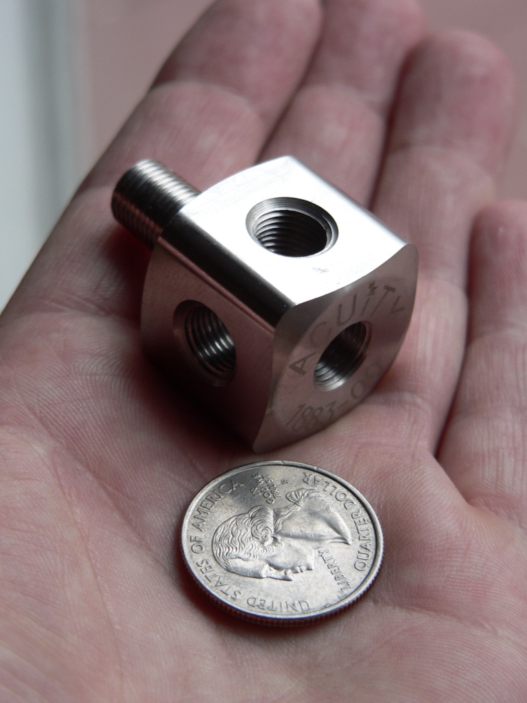
After a lot of thought, I decided the Acuity Instruments 1/8” BSPT to 1/8” NPT Oil Cube would be the best adapter to accommodate the oil switch, an oil pressure sensor and an oil temperature sensor. Its compact design and stainless steel construction make it the best choice for durability and economical use of space. It is capable of accommodating up to five sensors without protruding a great deal but two female ports cannot be used because of proximity with the lower fairing and the oil filter. Having holes on all four sides, there will never be a problem tightening it to a position where the holes are accessible in the cramped location this part needs to be installed. I also got very good sales communication and modification advice from Russ, the K-Series tech support person. Like any of the other adapters, it requires modification but I really think this one is the way to go if you plan to use an adapter instead of drilling a port in the engine yourself.
The modifications will address reducing the oil cube’s thread diameter (virtually all adapter’s will have a male port that is too big) and converting the thread pitch.
1/8” BSPT v 1/8” NPT
1/8” means that that the nominal diameter (inner diameter of the pipe) is 1/8 inch. Both 1/8” NPT and 1/8” BSPT pipe and male ports on adapters have a 1/8” ID but fittings such as elbows and nipples seem to often have a much larger nominal diameter.
BSPT stands for British Standard Pipe Tapered. It has threads that get progressively smaller (taper) so that they seal when male and female threads are tightened against one another. BSPP threads are parallel like the threads on a bolt. BSPP threads are not designed to seal on their own and they are not interchangeable with BSPT.
NPP is also parallel thread and it should not be confused with NPT because the two are definitely not interchangeable. NPT stands for National Pipe Tapered. Designed in the US, NPT is tapered to seal like BSPT but the angle of the threads is not the same. NPT threads are cut to 60° and BSPT threads are cut to a slightly narrower 55°.
1/8 NPT has 27 threads per inch and 1/8 BSPT has 28 threads per inch. The two are similar enough that they will thread together quit well but NPT and BSPT might not form a seal in high pressure applications.
There are also cut threads and rolled threads. Rolled threads are cut and then compressed into a rounded shape. I have no idea how well the rolled and cut threads seal when intermixed.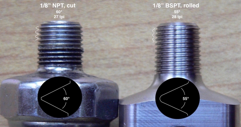
There is another pipe thread often used in China and Japan called JIS (Japanese Industrial Standard) and it is identical to BSPT. Metric pipe thread (M10, M8, etc) is sometimes used, too. Metric pipe thread is not tapered but seals with a gasket or o-ring.
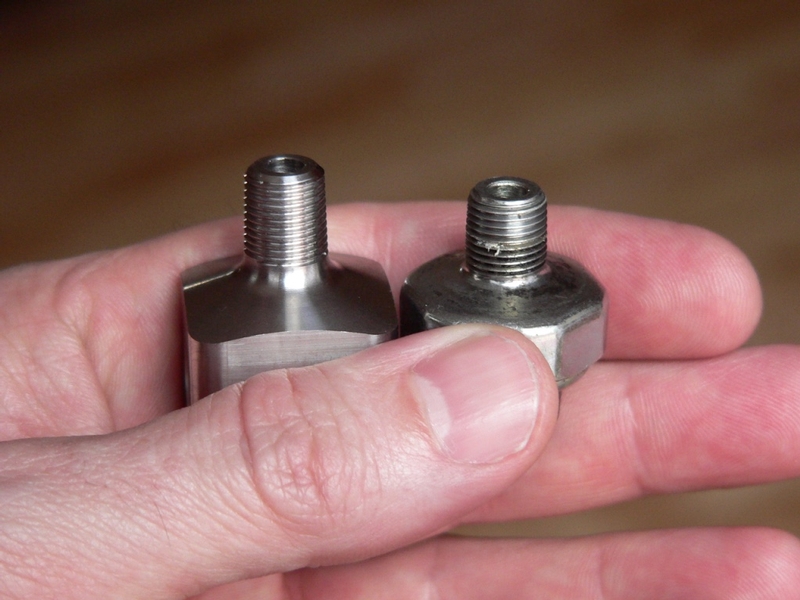
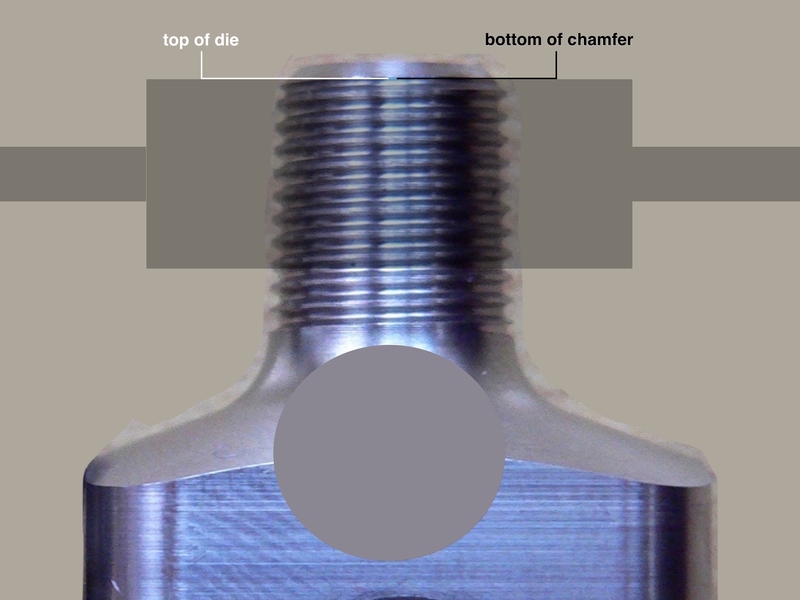
Oil Switch threads compared to the Oil Cubes Threads
The threads of the oil switch seem to mesh with the threads of the Oil Cube about as well as the oil switch threads interlock with another 1/8” NPT thread. Both threads are tapered. The oil switch threads are rounded at the top and they form a ram’s horn helix at the very tip. 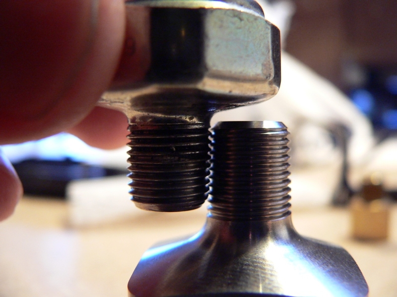
Threads interlock and are both tapered.
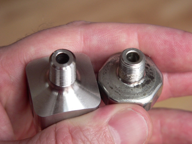
The oil switch threads round in at the tip creating a dome shape.
The oil switch threads form a helix at the tip and the cube’s tip is smoothly chamfered.
I measured the threads of the oil cube male port and the threads of the oil switch and found that the first two oil switch threads do rapidly reduce in diameter while the remaining threads change in diameter at a fairly regular rate almost identical to all of the threads on the oil cube port.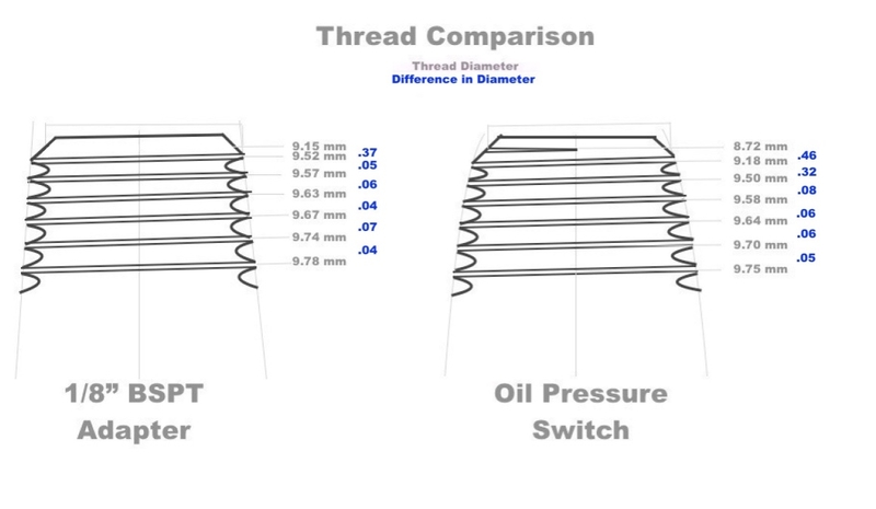
The difference between NPT and BSPT is not too hard to understand but the difference in the threads at the tip of the oil switch compared to the oil cube seem puzzling at first. The reason for the difference is the same reason that nothing will thread into the oil switch hole except the oil switch: the oil switch threads are cut extra small. The die that was used to cut them was the proper taper, threads per inch and thread pitch but the taper goes down to a smaller diameter than standard tapered pipe fittings. For this reason, the chamfer at the tip of the oil switch actually has the beginning thread cut in it. This causes the helix and the domed shape. Neither are important for sealing but they are simply the result of cutting the threads to a smaller diameter than they typically are cut.
The foremost difference between the 1/8” BSPT threads on the oil cube and the 1/8” NPT threads on the oil switch is the diameter of the threads. The oil cube should thread into the oil switch boss but the oil cube male port is too big to even start. The second difference between the threads on the switch and the cube is the angle and the oil cube threads are rolled where the switch threads are cut. Lastly, the threads per inch between the two is slightly different but that is probably less of a factor given that either will only need to thread in approximately one-fourth inch. As far as I know, the taper angle is the same between the two.
The problem of the oil cube male port being too big can be solved by threading it smaller with an adjustable die. Since the threads per inch is so similar and the taper angle is the same, we can use a 1/8” NPT adjustable die to reduce the diameter of the 1/8” BSPT threads. This will transform their pitch to 1/8” NPT at the same time. It all just sorta works!
OIL SWITCH THREAD PITCH MYSTERY
Do First:
Remove oil switch
I highly recommend you watch this video if you have never used a threading die before. This video deals with using a die to cut parallel threads but the technique is the same for tapered thread. Do not spin the die over tapered pipe thread like the guy in the video does with his bolt. The die could easily damage tapered threads if it is removed hastily.
Tools:
Oil Sensor Adapter (Acuity Oil Cube recommended)
small allen wrench or micro screwdriver
adjustable 1/8” NPT die
die wrench that has 180° set screws
screwdriver
masking tape
1/8” dowel or other object
two sheets of brass, plywood or cardboard
thread cutting oil (Tap Magic recommended)
compressed air
digital caliper
beer can
stiff cardboard
razor knife
round needle files
rat tail file
square needle file
1. Adjustable dies often have a screw pin that keeps both sides of the die flush as it is adjusted. Use a small allen wrench or micro screwdriver to adjust the pin on your adjustable 1/8” NPT die so that the head protrudes a bit farther than the width of the split in the die. This should permit the die to close all of the way without crushing the pin.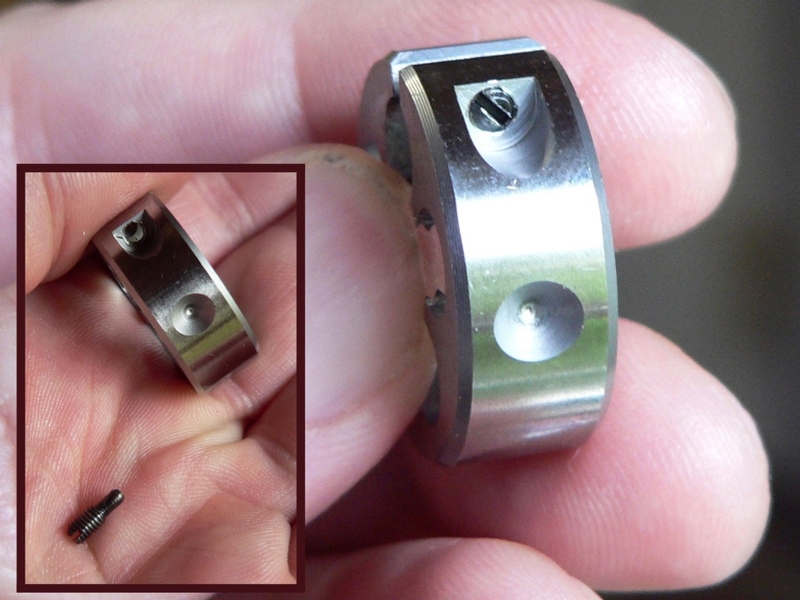
2. Place the die in a die wrench that has 180° set screws so that the points on the set screws engage the detents on both sides of the die.
Use a screwdriver to tighten the set screws so the die is secure but not tight enough to reduce its cutting diameter. You may engage the center set screw to the split to help secure the die and so that it cannot close.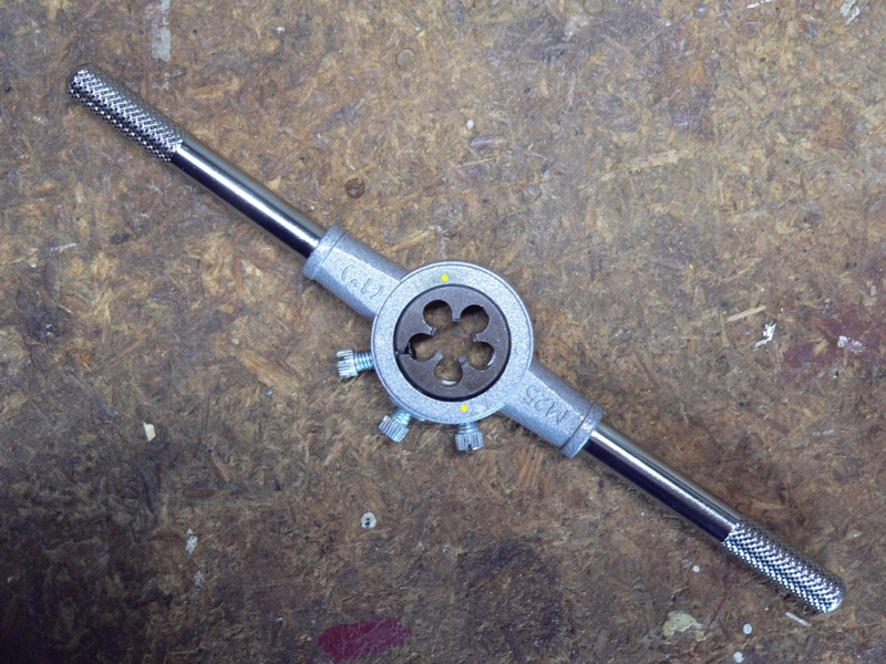
An adjustable die with a set screw pin will have detents that are situated 180° of one another (marked by yellow dots). This die wrench was designed to hold dies that have detents situated at 90° of one another. It works for 180° detents but only one detent can be engaged. A die wrench with two set screws opposite of one another would be better for dies with 180° detents.
3. Cover all female ports with masking tape and plug the male port with a 1/8” dowel or other object.
Tighten the adapter in a vise between two sheets of brass, plywood or cardboard. 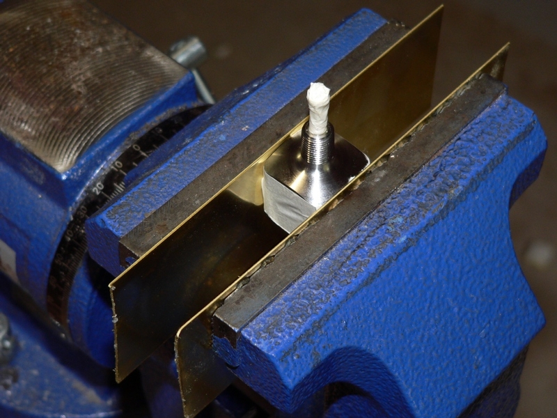
4. Lube the threads of the male port with a thread cutting oil.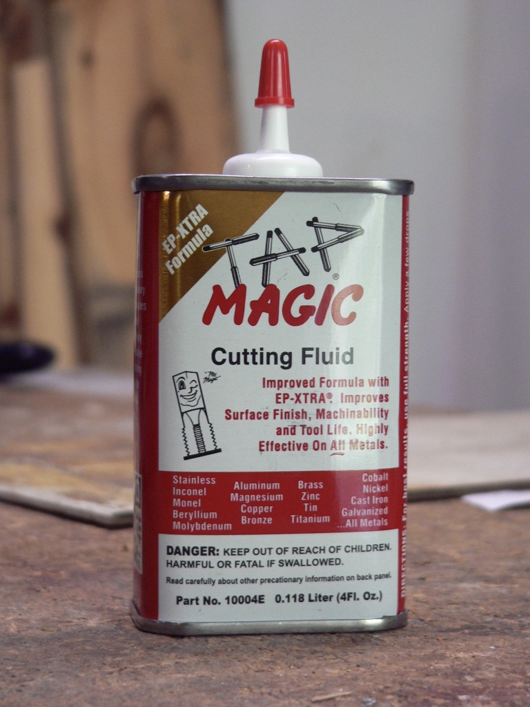
Tap Magic cutting oil is difficult to find but highly regarded by pros.
Carefully turn the starter threads of the die (the largest threads) onto the first threads of the male port. Be extra careful that the threads engage flush. The threads on the port will be ruined if the die is run down cross threaded.
Turn the die wrench clockwise until you feel it start to cut. Turn clockwise one-half turn more and then turn back counterclockwise one-quarter turn.
Continue turning one-half turn clockwise and one-quarter turn counterclockwise. Occasionally you may place a couple dabs of cutting oil at the top threads of the male port but try not to wash the shavings down the cells in the die or they could damage the threads as they are cut.
I have marked the highest tooth on the die (the last one that enters the threads) in the photo below. Stop threading when this tooth is even with the bottom of the chamfer on the male port. This will use all cutting teeth on the die and achieve the smallest possible diameter for the current adjustment of the die.
Stop cutting the threads at this same point each time you adjust the die smaller. 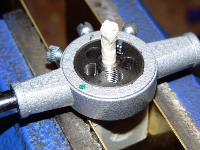
DO NOT run the the top of the die (smallest thread) down lower than the bottom (largest diameter) of the chamfer. If you do, threads that exit the top of the die will all be the same diameter like parallel pipe thread and they will not seal with tapered threads.
You will notice that a thread starts to be cut on the chamfer when the die is adjusted small enough. That is normal. Since the chamfer is tapered even more than the threads are, the thread that starts on the chamfer is irrelevant. It will not engage with the threads in the boss. You will see the same effect on the threads cut into the OEM oil switch’s chamfer.
5. Carefully thread the die off of the male port (do not spin the wrench like a propeller).
Blow all metal shavings out of the cells with compressed air before you use the die again.
Also blow all metal shavings from the threads on the male port.
6. Use a digital caliper to compare the smallest thread diameter of the oil pressure switch to that of the male port on the adapter. 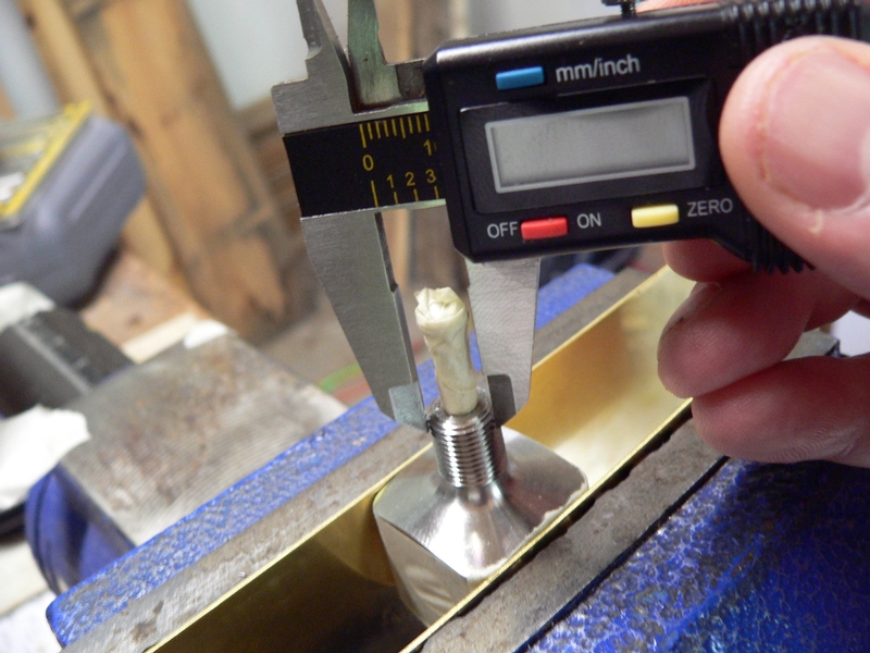
Test the male port in the oil switch boss. When it is the same diameter as the oil switch the male port on the adapter should thread in two and one half 360° turns before light resistance is felt.
7. Tighten one set screw on the die wrench about 1/4 turn to reduce the cutting diameter of the die.
You might need to adjust the set screw(s) in much smaller increments as the cutting diameter gets smaller or else it may become difficult to cut. The die seems to take off exponentially more metal as the settings get smaller. I believe this is because the die both closes and deforms to an oval shape at very small cutting diameters. Ninety degree detent dies are probably a lot better in this regard.
As the die gets squashed into an oval, you may notice that the teeth in one or two cells in the die seem to be doing most or all of the cutting. The threads that are cut will still be round because you are turning the die in complete circles.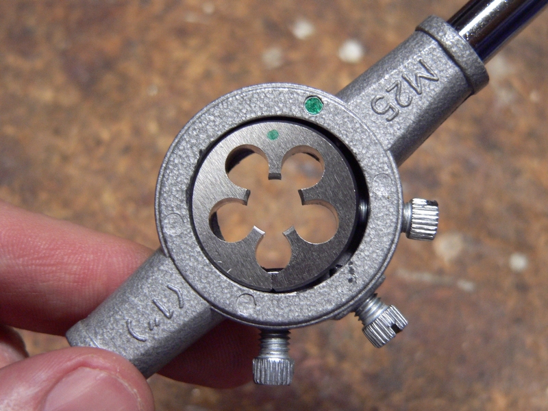
Repeat steps 4, 5, 6 and 7 until the adapter’s male port is the same size and test fits to light resistance with the same number of turns as the oil switch male port. My adapter threads ended up being a bit smaller than the oil switch threads. The adapter freely threaded in 3 complete turns after the final cutting with the die set to absolute minimum.
I would avoid making the adapter’s male port a lot smaller in diameter than the oil switch male port. There is plenty of very strong stainless steel left in the male port after threading to the size for the oil switch boss but if it were to be cut much smaller, it could become vulnerable to cracking. 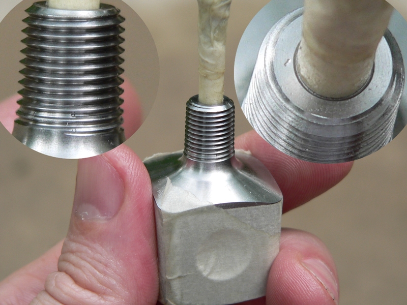
8. It’s likely that the force of working the die pushed up a bur or deformed the beginning thread in the chamfer where there is insufficient metal to form a complete crest. A needle file and shield can be used to soften this area although it’s doubtful it will make contact with any of the internal threads.
Cut open a beer can or light sheet metal and snip out a 2” x 1” piece to use as a filing shield.
Tape the metal to a piece of stiff cardboard and start a hole by twisting the point of a razor knife into the metal. Don’t try to drill it, it will catch and spin.
The hole will have to be big enough to fit loosely over the first thread on the male port of the adapter. Use round needle files and a rat tail file to finish the hole.
9. It will not matter that this first bit of thread is dulled. It would have no impact on sealing anyway.
Place the shield over the first thread.
Use a square needle file to flatten off the sharp edge on the crest of the first one-half to three-quarters of thread. This is delicate work. There is no need to apply a lot of pressure.
It’s doubtful that the port will ever thread in far enough to contact the last threads but you can use a triangular needle file to smooth out the burs left where the die stopped on both sides of the male port. Just the last two or three threads if you feel a bur with your fingernail.
When finished, blow the threads off with compressed air.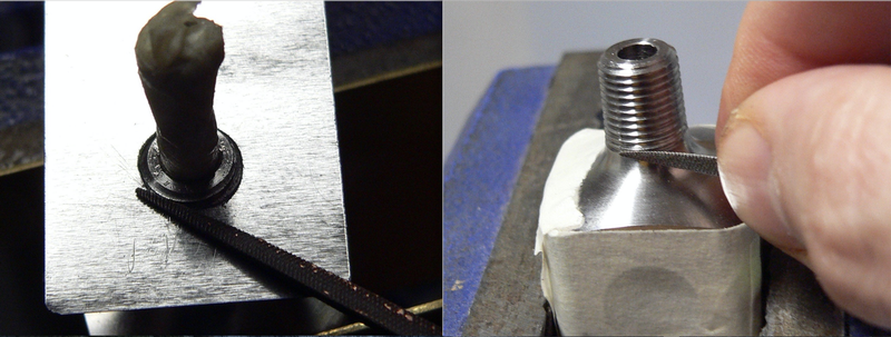
10. With the ports all having been covered, it’s unlikely that any metal shavings could have been deposited inside but bathe the cube in mineral spirits to make sure. Blow the mineral spirits dry with compressed air and then let it sit a few hours to be sure all moisture is dried up.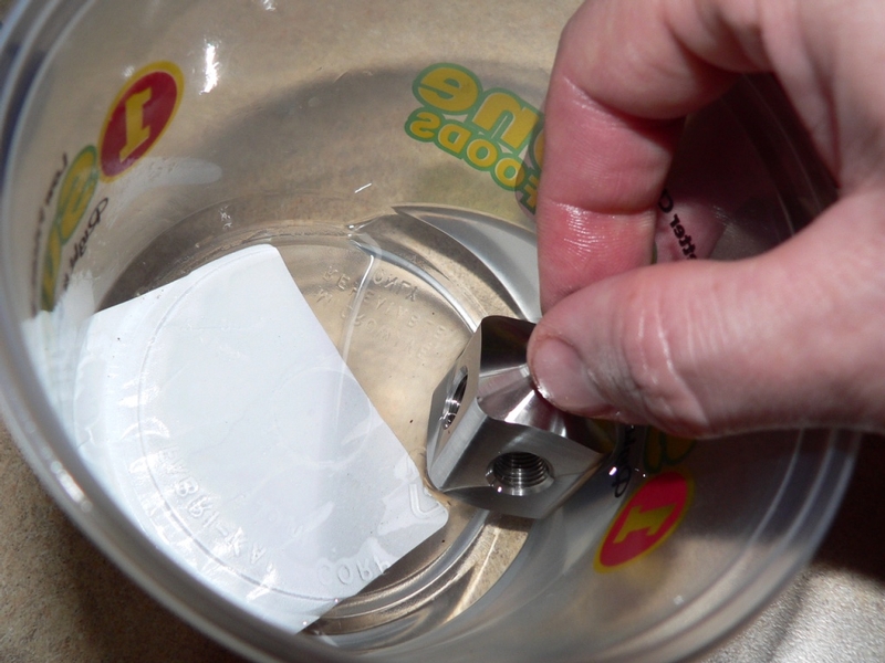
11. The hollow brass plug that will fit in the port opposite of the oil temperature sensor may need to have its hole enlarged to admit the tip of the oil temperature sensor probe (but be forewarned, oil temp sensors work poorly unless installed right in the motor).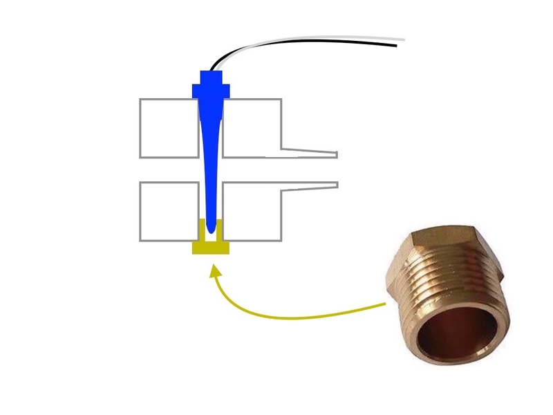
I used a diamond bit in a dremmel that was held in a dremmel stand to enlarge the diameter of the hole in the plug. The reduction in the thread wall thickness should be safe because the hole in a standard brass nipple is large enough for the probe to pass through.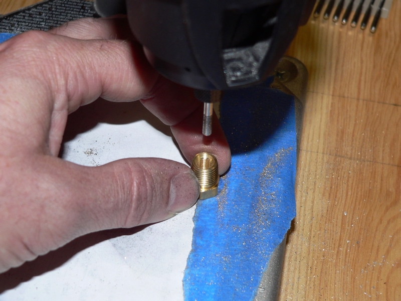
13. Use a mill file to create a 45° chamfer around the tip of the plug if there is not one already there. The delicate thread at the tip is vulnerable to getting shaved off when the plug is installed and this will contaminate the engine. Remove any burs with emery paper.
Blow the shavings off the plug.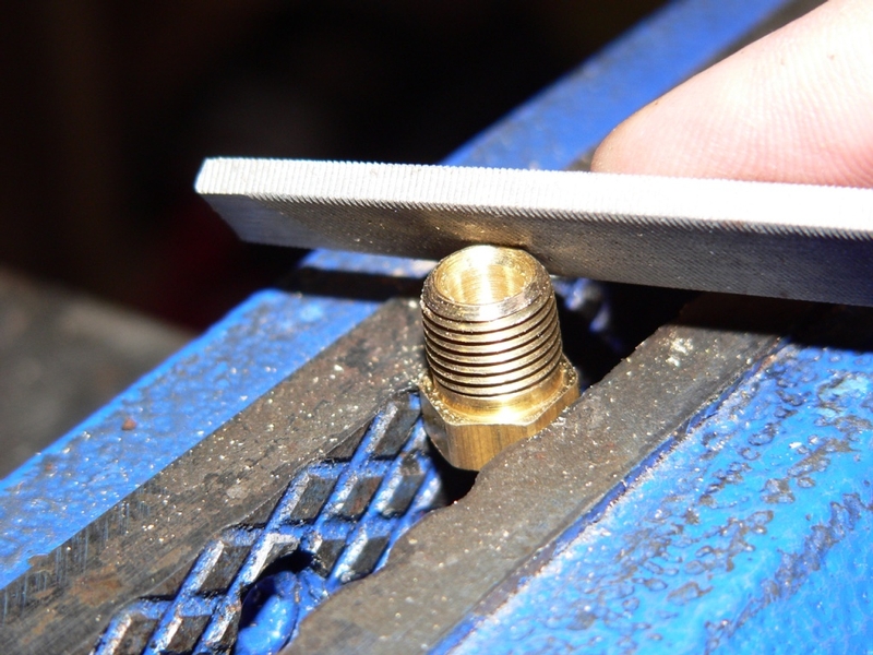
The front female port of the cube has 1/8 BSPT threads. If a 1/8” NPT sensor is required to fit in it, a stainless steel 1/8 male BSPT to 1/8 NPT female adapter may be used between the port and the sensor. This will increase vibration of the sensor, add weight and make the sensor in the front port extend another half inch but it is the best way to ensure a good seal.
It is not possible to convert the front female port’s threads to NPT. I do not believe a 1/8” NPT tap could achieve this because there is only enough depth inside the cube to run a tap approximately one-quarter inch past the inside wall. The tap would probably hit the opposite inside wall before the front female port threads were completely cut into NPT. Also, the port’s thread diameter would become too big to seal with any standard male NPT fitting. The male NTP threads on the sensor cannot be converted to BSPT for the same reasons and I had less satisfactory results cutting NTP to BSPT than the other way around. It seems that cutting 28 tpi BSPT to 27 tpi NTP works but going from 27 tpi to 28 tpi causes the complete removal of one thread after the first 6 threads are converted.
I simply installed the 1/8 NPT sensor with medium density high temp PTFE tape to the 1/8 BSPT female port and it sealed(see OIL GAUGES INSTALL, step 5).
To accommodate a maximum of three sensors, the oil cube should be installed so that the side ports face approximately 45° above and below horizontal when the bike is standing vertical (a diamond shape when viewed from the front). Although there are five female ports in the cube, each one is fairly specific concerning what kind of sensor can or should be installed to it.
port 1 The oil switch wire will only reach the top side port that faces to the left.
port 2 No sensor will fit here because of tight fairing clearance. However this port has a special purpose if an oil temperature sensor is installed. Port 2 holds the hollowed out plug that is necessary to fit an oil temperature sensor probe.
port 3 This port needs to be plugged. It can’t hold a sensor because of tight clearance with the oil filter. If a sensor could be installed in port 3, it would be more susceptible to damage from flying road debris than sensors in any of the other ports.
port 4 Being located between the oil cooler and the oil filter, this is a bit warmer and there is not enough clearance for sensors that protrude more than a half inch. A small sensor can be installed here. Since the hollowed out plug in port 2 can accommodate a probe from this port alone, it is the only choice for an oil temperature sensor which fortunately is usually pretty small.
port 5 Any sensor that does not have a probe can go here. A sensor with a probe installed in port 5 might obstruct the hole from port 6 unless an adapter is installed to extend port 5. It is probably less desirable to install a sensor with a probe to such an adapter because most of the probe will be housed within the adapter. Port 5 has 1/8” BSPT threads so there could be a problem sealing with 1/8 NPT unless the proper adapter is installed between port 5 and the sensor. I used teflon tape on the threads of my 1/8 NPT sensor and the joint sealed.
port 6 The male port on the cube has 1/8” BSPT threads which must be reduced in diameter and converted to 1/8” NPT in order to fit the oil switch boss.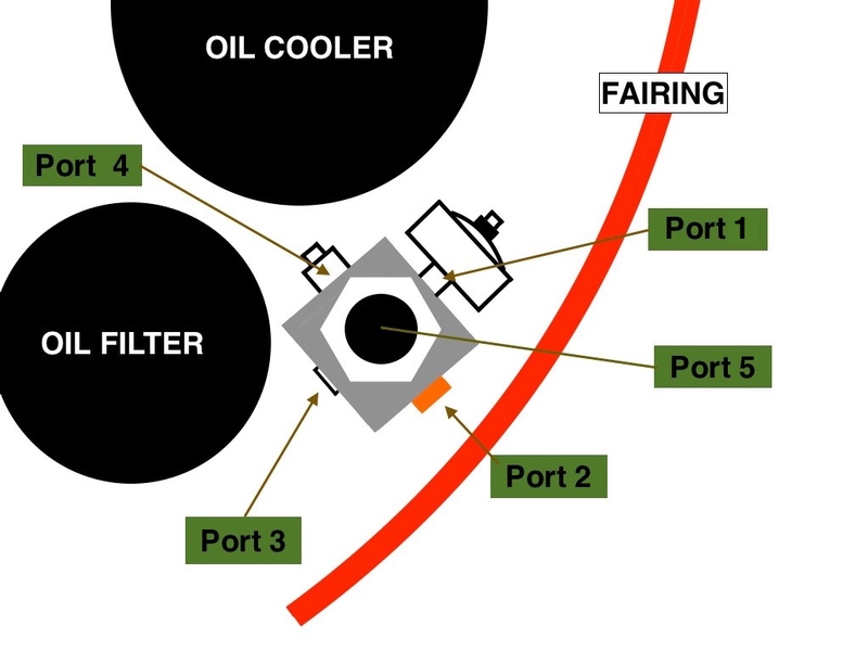
* Last updated by: Rook on 9/3/2017 @ 7:13 PM *