


Camshafts Removal and Installation
There is a separate camshaft for the inlet valves and the exhaust valves. The Camshafts may be removed to perform a variety of tests to determine wear to the camshafts and related parts.
Maintaining the exact relationship of the camshafts to one another and to the crankshaft is crucial. This relationship is called engine timing. If the camshafts are out of time with the rest of the motor, the valves will not open and close as they were intended. Severe engine damage results if the motor is run with the engine out of time. In certain situations, engine timing is deliberately altered very slightly to change performance. This is called timing advance or timing retard.
When the camshafts are removed, take care to not drop them or scratch the journals (the journals are the surfaces that the shafts rotate on in the head).
Do First:
Remove Foremans, ram air covers, tank cover, side fairings and lowers.
]Remove PAIR system (PAIR Removal, steps 4-7)
Remove Fuel Tank, steps 1 through 6.
Remove Throttle Cables, steps 1 through 9.
Remove Throttle Bodies, steps 1 through 9.
Remove Engine Heat Insulator Rubber Plate, steps 1 through 3.
Remove Stick Coils , steps 1 through 3.
Remove head cover, steps 1 and 2
Tools:
plastic bags
5mm hex tool
three 10” bungee cords
paint
garbage bag
tape
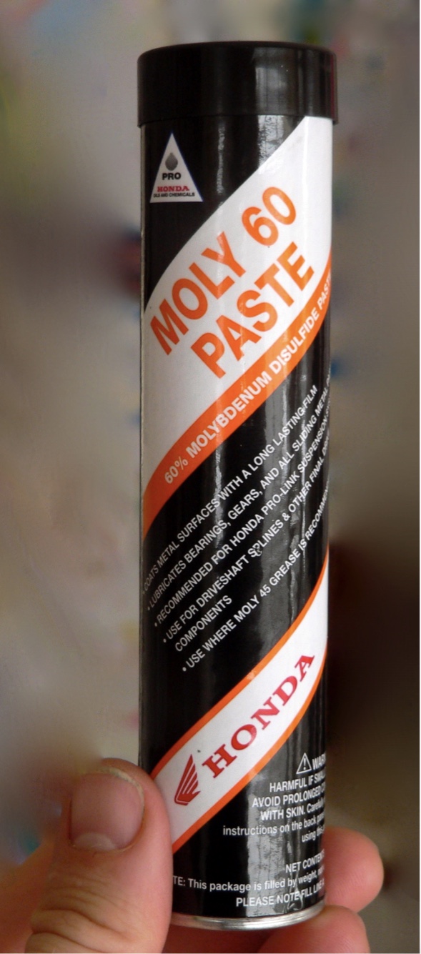
molybdenum disulfide grease
5 mm allen wrench
20-200 in lb torque wrench
Removal
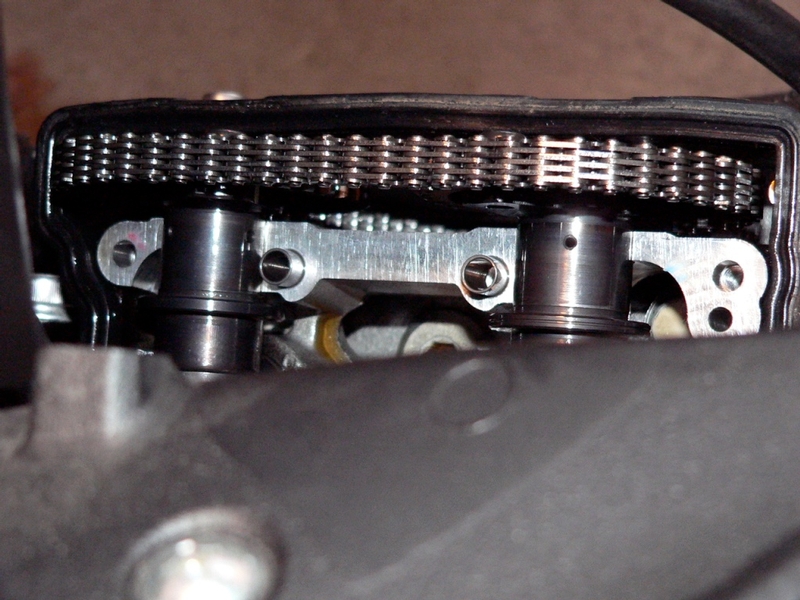
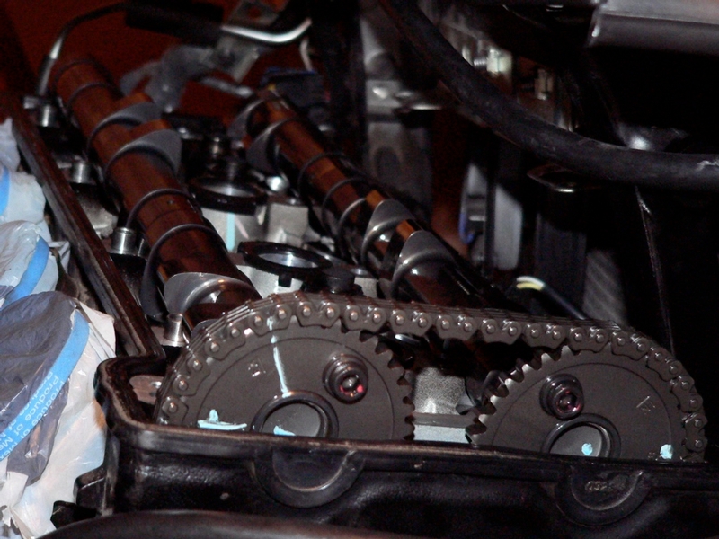
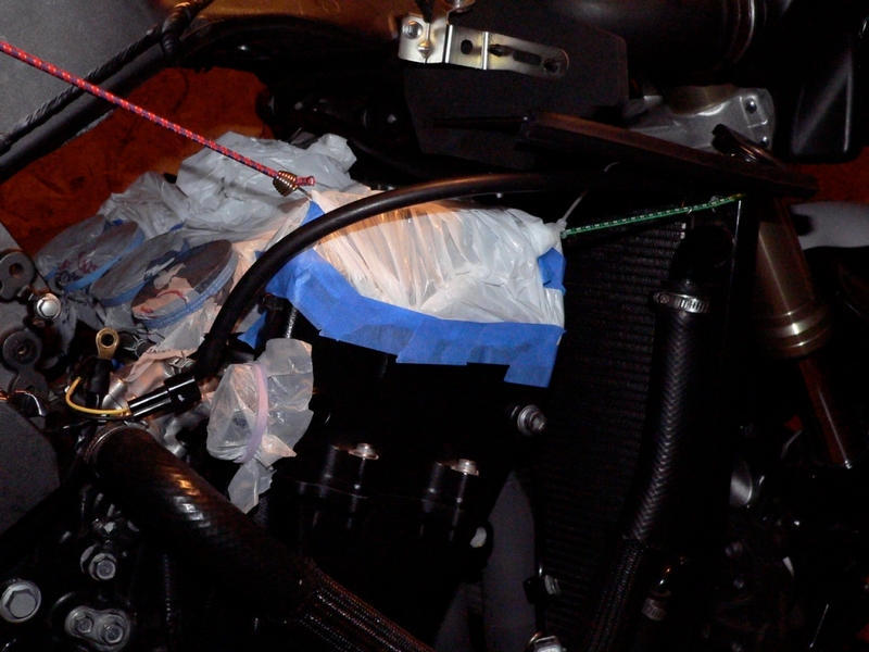
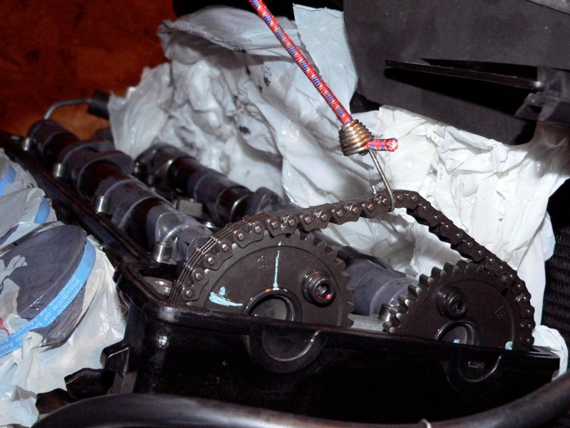
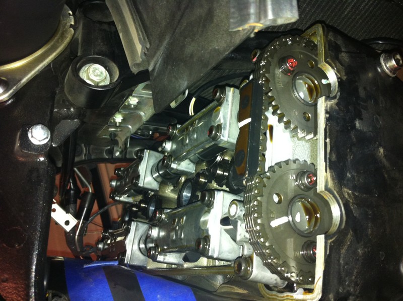
1. Remove the crankshaft sensor cover, turn the crankshaft sensor rotor to #4 piston TDC (Crankshaft Sensor, steps 1 and 2. The Cam chain sprockets should appear as shown in the photo below. A timing mark on each sprocket should be to the outside and parallel to the top of the engine case. There is also a mark on each sprocket that is approximately 45 degrees to the top of the engine case. If the timing marks on the cam chain sprockets do not appear as shown, the crankshaft is set at TDC piston #1. Turn the crankshaft sensor rotor 360 degrees and the engine will be set at TDC #4.
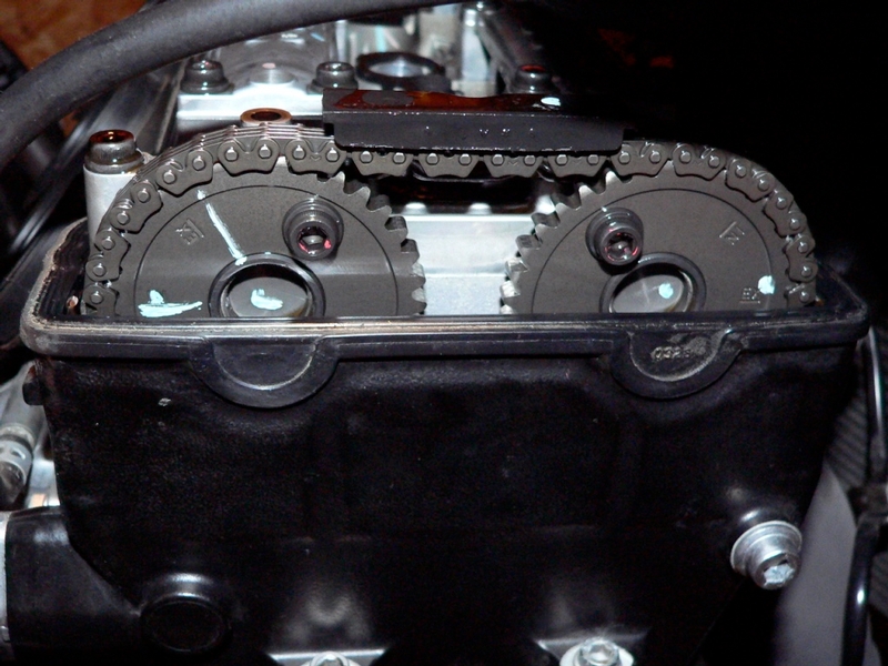
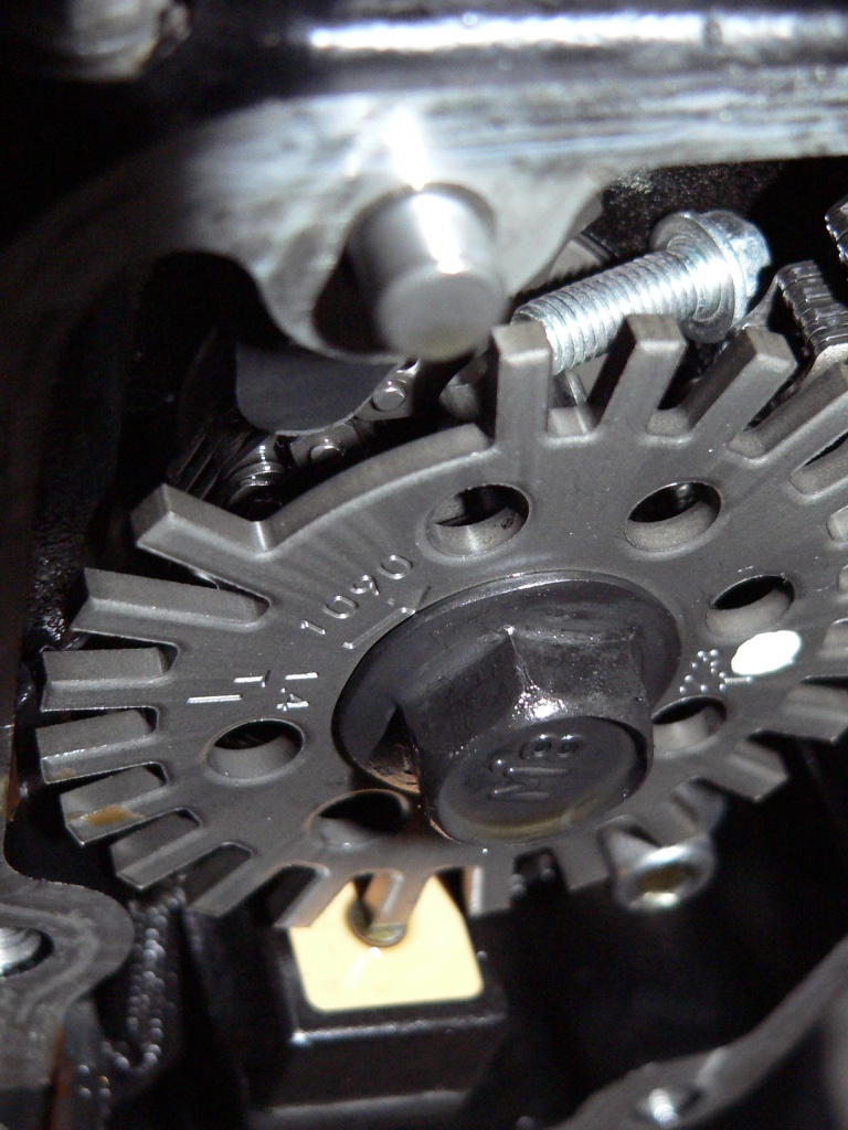
Be careful not to drop any of the screws or other small parts into the cam chain tunnel . It is a good idea to stuff rolled up plastic bags all around the cam sprockets to prevent anything from falling inside. If any small parts do fall down the cam chain tunnel, they will most likely come to rest behind the timing rotor (note the loose screw to the right top of the timing rotor in the pic)(see Crankshaft Sensor Positioning, steps 1 and 2). Plug the spark plug holes in the same way to prevent small objects or debris from entering.
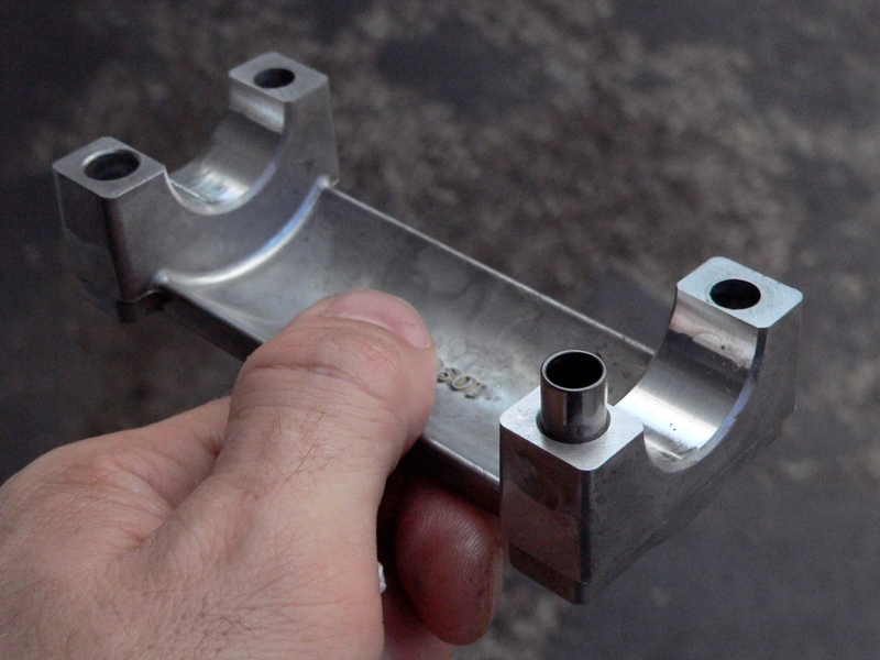
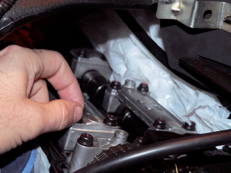
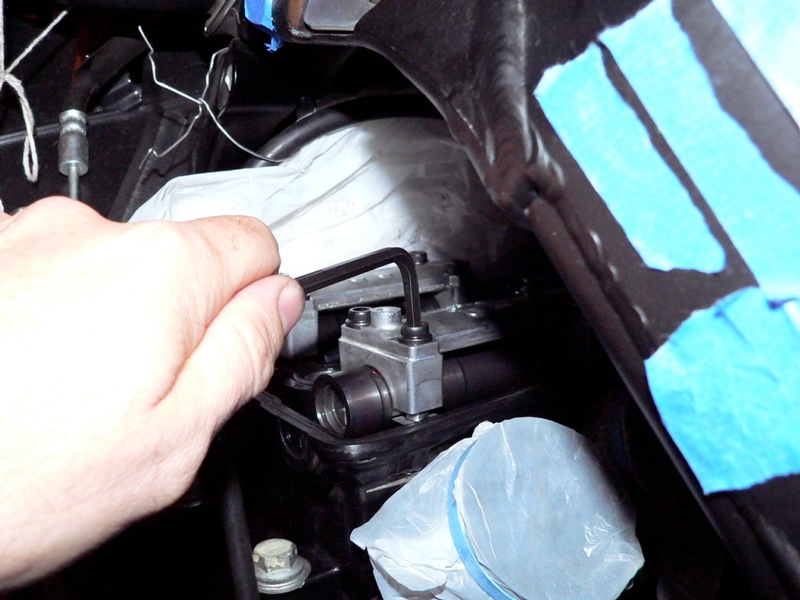
2. Use a 5mm hex tool to remove the 4 screws and cam chain guide from the far right camshaft cap [B] which spans both cam shafts. Leave the two dowel pins in position in the head as shown in photo G2 below.
Diagram CSC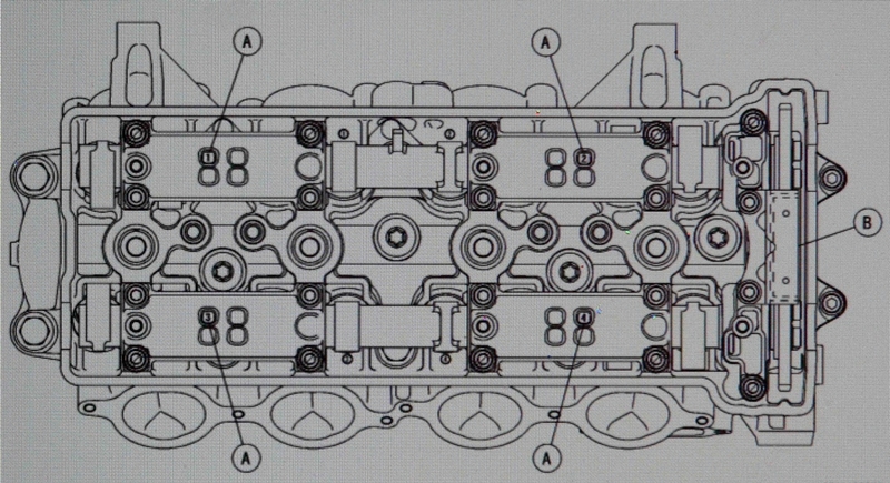
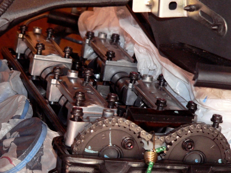
There are 4 main cam shaft caps {A}. They are numbered 1,2,3,4. The number is molded into the top of each cap. The 5th cap is the chain guide cap {B} on the right.
photo G1
chain guide and right camshaft cap
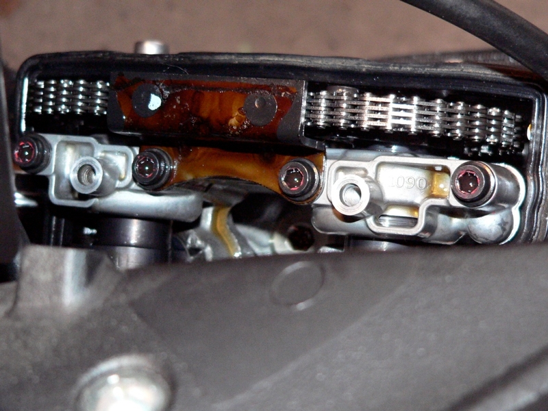
photo G2
right camshaft cap removed, dowel pins left in place
3. Each camshaft cap has 4 bolts. Each cap is positioned on two dowel pins. Using a 5mm hex tool, remove the bolts from the two center cam caps, cap 2 and cap 4 (see diagram CSC, in step 2)and remove the caps being careful not to lose any of the dowel pins.
You may leave the bolts hang in the camshaft caps when you lift the caps up. With the bolts left in as guides, you will be able to see if the two small dowel pins are getting pulled out of the engine as the cap is removed.
Diagram DP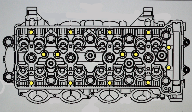
The location of the dowel pins are marked by the yellow dots in the diagram above.

Dowel pins safely remaining inserted in the mating holes of the head.
Some dowel pins may gently cling to the mating hole in the cam cap. Be careful not to drop any dowel pins out if that should happen.
4. Remove the bolts from the far left caps, cap 1 and cap 3. Thread the four bolts in each cap out very evenly in an X pattern. Turn each screw approximately 1/2 turn at a time so as to minimize binding with the cam shaft. If a cap should bind on the dowel pegs, tighten one or two of the cap bolts back down a small amount until the cap releases. Never pry a cap up to free it.
There is upward pressure caused by the valve springs under each camshaft. With the engine positioned as it is at TDC #4, the cam lobes will be situated such that the left ends of the shafts are lifted higher than the right. This will make lifting the cam chain sprockets out from under the cam chain easier.
5.Remove the Cam Chain Tensioner (see Cam Chain Tensioner Removal,steps 1-4).
6. Lift the cam chain off of the intake sprocket and apply a 10” bungee cord to hold it in place and maintain tension on the chain. DO NOT ALLOW THE CAMSHAFT CHAIN TO COME OFF OF THE SPROCKET ON THE CRANKSHAFT BELOW. Tilt the left end of the camshaft up and out of the head then lift the right end out from under the camshaft chain.
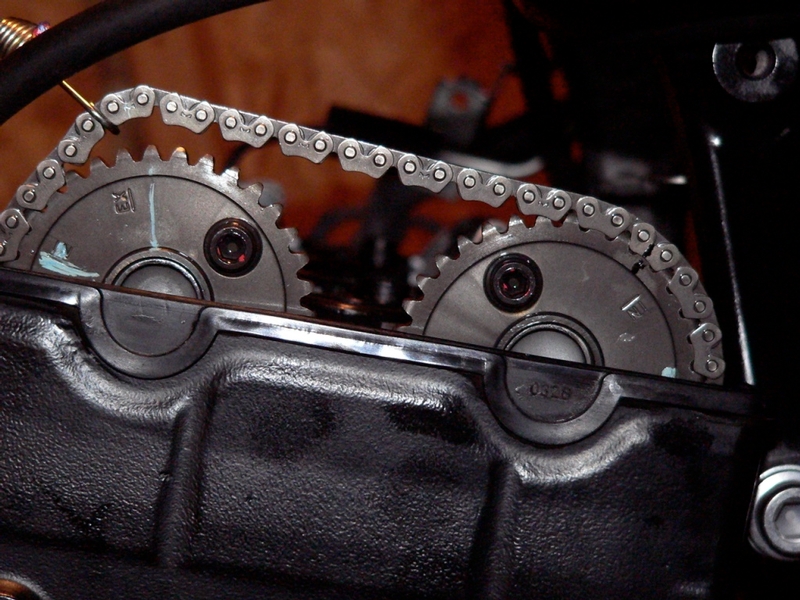
My intake camshaft sprocket was marked at the factory. There is a white line painted on the sprocket marking the tooth to the inside of the embossed EX on the sprocket. The white line continues onto the link in the cam chain that is aligned with that tooth. I marked the exhaust in a similar fashion using black paint. This will help to reinstall the cam shafts so that the timing is exactly as it was before removing the camshafts. Note that marking a chain link to a sprocket tooth only works if the motor is left unturned throughout the procedure. The difference in the number of teeth on the crankshaft sprocket and the camshaft sprockets will cause the marks to misalign if the engine is turned. They would only line up as marked after the engine had been turned dozens of revolutions.
Paint does not adhere well to the metal. Be extremely careful when handling the camshafts so that the paint marks do not become rubbed off. Making large marks will also minimize the chance of them becoming obliterated.
7. Apply a second bungee over the exhaust camshaft. Remove the exhaust camshaft in the same way as the inlet camshaft was removed.
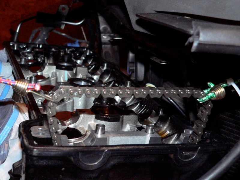
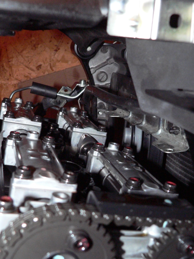
The front bungee is secured to the radiator filler cap. The other is two bungees joined together to double the length. They are are routed over the top of the air box and are secured to the two hose fittings at the lower left bottom of the air box.
8. With the bungees in place, the head cover will no longer be usable as a dust protector. Protect the motor from foreign objects by Wrapping the open head in a garbage bag and tape it all around.
Camshaft Installation
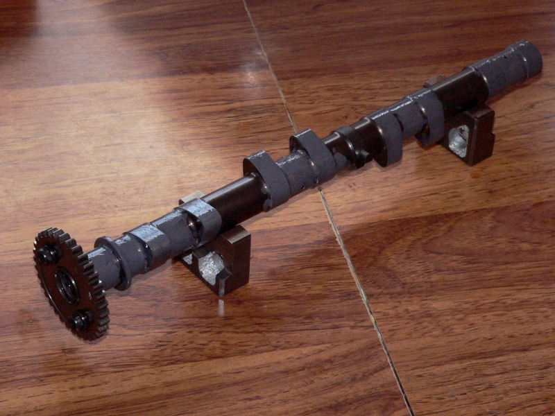
The Camshafts may be identified by the 1090IN (Inlet) or 1090EX Exhaust) cast on the cam sprocket mounting bracket. Also, the Exhaust Camshaft has a small projection protruding from the center. Be sure to install the Camshafts on the proper side of the motor.
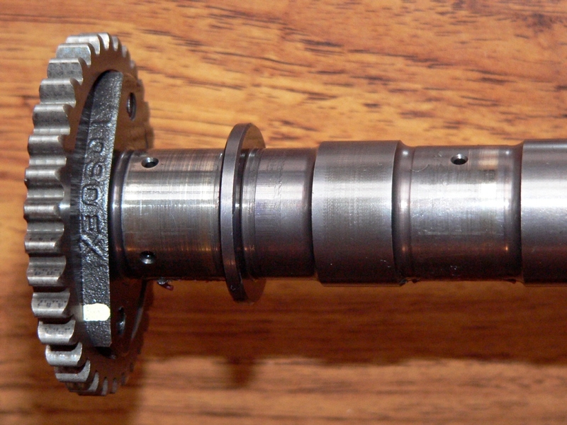
Exhaust camshaft, 1090EX
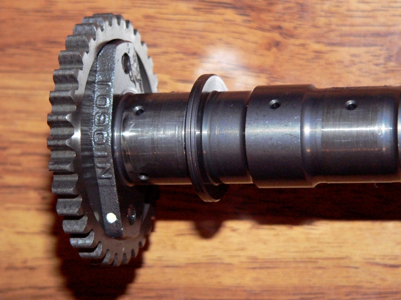
Inlet camshaft, 1090IN
9. Coat the journals and cam surfaces of both camshafts with a solution of approximately 50% motor oil and 50% molybdenum disulfide grease. If a new camshaft is installed, apply a thin coat of molybdenum disulfide grease to the cam surfaces. (mixture of engine oil and molybdenum disulfide grease in a weight ration is 10 : 1 according to the service manual).
I did not replace the camshafts but I coated all the journals and the cams with the molybdenum disulfide and oil solution anyway.
10. Make sure all dowel pins are placed in the head according to the diagram DP in step 3 above.
Place camshafts back in. Using the paint marks applied in step 4, line the teeth up to the same cam chain link as when the camshafts were removed. Install the camshafts by tilting them toward the timing chain so that the timing sprockets can be more easily engaged with the chain before the the journals are placed into the head. The camshafts will rest in the head with the left side above the lifters and the right journals laying close to the lifters. This is because of the way the cam lobes are positioned and because the valve springs have opened up and caused the lifters to rise. Tightening down the camshaft caps will compress the valve springs as they were when the camshafts were removed.
Use a bungee cord to maintain tension on the timing chain. Do not allow the chain to jump teeth or fall off of the crankshaft sprocket below.
11. Position the four numbered camshaft caps (1, 2, 3, 4), chain guard cap and cam chain guard according to diagram CSC in step 2 above. Seat the caps on the dowel pins at the locations marked in diagram DP in step 3 above. Take care to not accidentally remove a dowel pin while placing the caps
Thread all 20 camshaft cap bolts in loosely.
12. Tighten the bolts with fingers only. The Camshafts will set into the head closer on the right over Cylinder #4 than they do on the left over Cylinder #1. The bolts at the far left will do most of the pulling to compress the lifters and seat the camshafts into the head. Tighten the bolts down as evenly as possible to avoid any binding.
13. When fingers will no longer effectively turn the bolts, use a 5 mm allen wrench to
continue gradually tightening the bolts and pulling the camshafts down into the mating surfaces in the head. You may press down on the left end of the camshaft to manually compress the lifters below. This will relieve stress on the delicate threads in the aluminum head while tightening the bolts. Tighten the bolts until you feel them make contact. Stop. Do not tighten past this point without using a torque wrench. The threads in the head are easily damaged by over tightening.
14. Use a 20-200 in lb torque wrench and 5 mm hex key socket to tighten the camshaft
cap bolts (spec: 106 in lbs) according to the sequence [circled numbers 1 ~ 20 in diagram TSCSC below]. Tighten the bolts in the proper order and a little at at a time to ensure that the caps seat evenly.
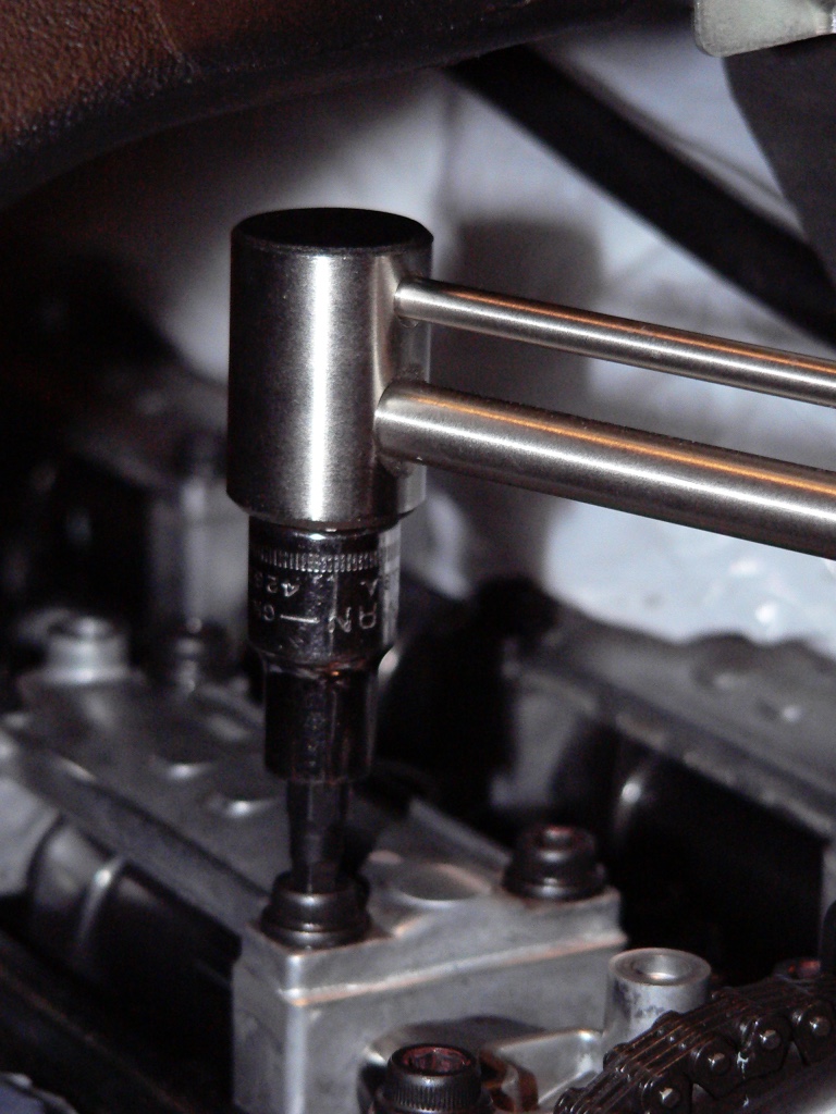
Diagram TSCS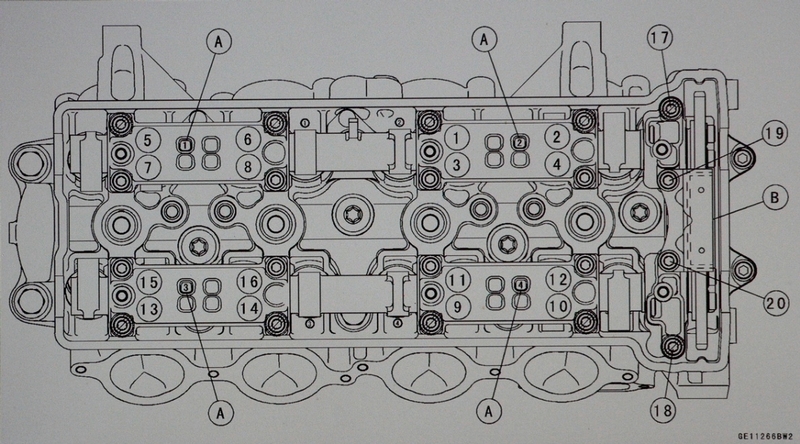
15. Install Cam Chain Tensioner, (See Cam Chain Tensioner Removal Steps 5-13)..
Remove the bungee cords.
Install head cover, steps 3-6
Install Stick Coils, steps 4 and 5.
Install engine heat insulator rubber plate, step 4.
Install Throttle Bodies, steps 10 through 15.
Install Throttle Cables, steps 10 through 20.
Install Fuel Tank, steps 11-15
Install PAIR system, (PAIR Removal, steps 1 through 7 reverse and steps 8 and 9)
Install Foremans, ram air covers, tank cover, side fairings and lowers
* Last updated by: Rook on 1/31/2018 @ 6:24 PM *
 mm Strawberry for me!


 maybe some day. I'm still a bit worried about messing with stuff too much.