'08 MIDNIGHT SAPPHIRE BLUE Now Deceased
 |
 |
 |
 |
 |
 |
 |
Created on: 01/13/12 02:14 AM
Replies: 64
Rook

Joined: 03/28/09
Posts: 20589
TrashHauler
Location: Downunder
Joined: 09/28/12
Posts: 41
Rook
Joined: 03/28/09
Posts: 20589
RE: Valve Clearance Check and Adjustment
01/03/20 7:13 AM
That is really cool, TH! Am I correct in stating the center adjuster screw cannot be replaced with an ordinary allen head machine screw? An allen hex would sure be easier to turn than that phillips/straight slot head. It looks as though that OEM center screw has threads with a stopper so the screw can only be turned X # of turns in and out. It also felt as though the center screw had some kind of stopper on it when I turned it with the T Bodies installed.
* Last updated by: Rook on 1/3/2020 @ 7:15 AM *
Proven001
Joined: 01/03/20
Posts: 1
RE: Valve Clearance Check and Adjustment
01/03/20 4:44 PM
Hi Guys, I'm new to the forum.
Firstly I wanted to tank you for the great 'how to write ups' it's given me the courage to attempt maintaining my bike. I also wanted to add that I am a complete novice when it comes this stuff, so please bear w/me.
I'm in the process of checking my valve clearances for the on my 2008 zx14 for the first time.
Question: when you are TDC for cylinder 1, should both the intake cams be in the same position? It looks like the furthest to the left intake cam and the one next to it are in different positions. I can measure the gap on the left cam, but can't measure the next one, the 'point of the egg' looks like it is touching the lifter.
I can try to take pictures.
Question 2, is it okay to measure the gap with the point of the cam pointing up? If YES, then I can measure intake valve gap 1, then 2 separately..
(i realize i sound like an idiot) Any help is appreciated.
Hub

Joined: 02/05/09
Posts: 13717
RE: Valve Clearance Check and Adjustment
01/03/20 8:29 PM
We sit on the bike and we use left and right to describe what switches we need to replace, or to stand on left side of bike, or the spark timing of 1-2-4-3, so 1 starts at the left.
The cam lobe nomenclature is heal and toe. So the pointed end is the toe.
Stand on the left side of the bike and look at number 1 cylinder's cam lobes. To measure the shim gap, the toes face out toward the exhaust and intake. You will adjust both in&ex on 1, then 2's ex and 3' intake.
You are going to turn the crank so 4 is at top dead center or toes pointing out. Measure both in/ex on 4, ex on 3, and in on 2.
Bend your feelers so they do not cock under the shim to cam lobe. Use the go-no-go system. Max feeler should not go in. You'll see the shim clearances stamped on the build card on the left side of the frame.
Where this is book cam position, yes, you might find the odd or single adjust lobe sitting up. Book still calls this a good measurement at this position.
TrashHauler
Location: Downunder
Joined: 09/28/12
Posts: 41
RE: Valve Clearance Check and Adjustment
01/03/20 10:13 PM
Rook - I think you could replace the screw but you would need a lathe to turn the end down as the screw has no thread on the end.
Proven 1 - a couple of times I mistakenly thought the same but I was actually looking at #1 right and # 2 left cam lobes. The key to remember is that each cam lobe for a cylinder sits either side of the cam bearing. You won’t see to cam lobes from the same cylinder without the bearing between them.
TH
Rook
Joined: 03/28/09
Posts: 20589
RE: Valve Clearance Check and Adjustment
01/04/20 2:03 PM
Rook - I think you could replace the screw but you would need a lathe to turn the end down as the screw has no thread on the end.
Rook
Joined: 03/28/09
Posts: 20589
RE: Valve Clearance Check and Adjustment
01/04/20 3:02 PM
Question: when you are TDC for cylinder 1, should both the intake cams [for cylinder 1] be in the same position? It looks like the furthest to the left intake cam and the one next to it are in different positions. I can measure the gap on the left cam, but can't measure the next one, the 'point of the egg' looks like it is touching the lifter.
If you have followed steps 1, 2, and three and your visual is the same as the each pic in steps 1, 2 and 3, that would have to be TDC of the compression stroke for cylinder #1. That's the correct engine position to check the valve clearances indicated in solid black in step 4.
Proven 1 - a couple of times I mistakenly thought the same but I was actually looking at #1 right and # 2 left cam lobes. The key to remember is that each cam lobe for a cylinder sits either side of the cam bearing. You won’t see to cam lobes from the same cylinder without the bearing between them.
That is a great observation TH. I think I had the same confusion when I did this.
The vertical legs of the camshaft towers hide the cam on the side facing away from you. It's like the cam's hiding behind that wall. You might be looking at the LH cam on Cylinder #2 and thinking that is the RH cam for Cylinder #1. I'll bet that's it. Have a look at the pic in step 7 and you can see that RH cam just barely peeking out around the corner of the camshaft tower. Also refer to step 16 and you can see how close those paired cams are to one another. The one you are looking for is just hiding on you! It's tricky to get a tape in there to measure the gap. You have to flex it and slide it in nice and flush to the lifter. You will struggle a bit to get the angle right but don't force the tape...it might just be too thick to fit. Have patients and you'll get it without scratching your lifters.
Seems to me, the lobes of both intake cams for any given cylinder would ALWAYS be exactly in the same position whether you were at TDC or somewhere else in the cycle. If you have one lobe up and one down, those are not partners on the same cylinder.
If the "point of the egg" (lobe) is pointed down that is not the correct position to check. If the lobe is touching, obviously you cannot check the gap, there would be no gap to get a feeler gauge in. What you are measuring when you check valve clearance is the space under the round portion of the cam, not the lobe.
Question 2, is it okay to measure the gap with the point of the cam pointing up? If YES, then I can measure intake valve gap 1, then 2 separately..
The illustration in step 4 shows which valves you can check when the the engine is positioned at TDC of Cylinder #1's compression stroke. The solid blacks in the diagram are the ones you can check at TDC compression stroke Cylinder #1.
To answer your question, I believe you could check the clearance at any point where the circular portion of the cam is over the lifter. Round is round---same clearance all along that curve as long as you are measuring under the round. You cannot check the clearance with any portion of the "out of round" lobe portion of the cam over the lifter. The lobe is not round and consistent like a circle is.
^^^ All hypothetical. Just get the motor positioned according to steps 1, 2, and 3 and you are ready to measure the LH intake cam of Cyl #1 and the RH intake cam of Cyl #1. The lobe on both will be pointed forward. Look closely, I think the RH intake cam is hidden from your view as mentioned by TrashHualer.
* Last updated by: Rook on 1/4/2020 @ 3:03 PM *
doubleD

Joined: 06/16/14
Posts: 390
RE: Valve Clearance Check and Adjustment
01/14/21 8:03 PM
Rook,
I found a video of a guy working on the C14. He does not take out the camshafts and somehow gets all the buckets out . Is that possible?
Looks like he does not remove the fuel tank or throttle bodies either.
I'm trying to get my confidence up to take apart and put the Bike back together.
With Covid still around now is the time to do this task.
https://www.youtube.com/watch?v=BRr19bcGyYM
* Last updated by: doubleD on 1/16/2021 @ 8:07 AM *
Rook
Joined: 03/28/09
Posts: 20589
RE: Valve Clearance Check and Adjustment
01/15/21 5:40 PM
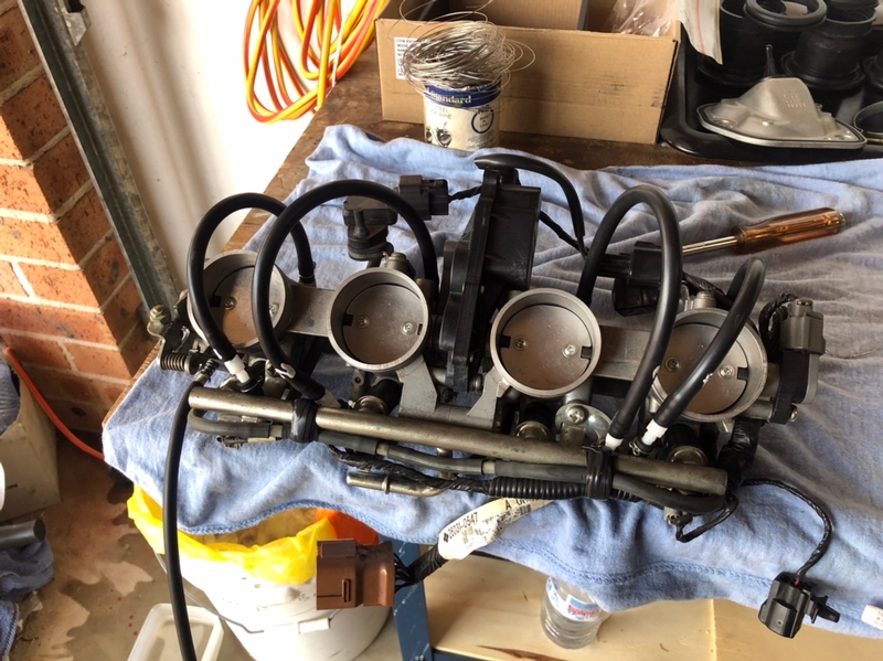
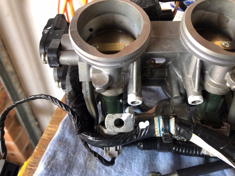
I'm not sure why I said to remove the fuel tank unless it was so to remove the fuel line to remove the t-bodies. You can remove the fuel line from the T-bodies instead but it's hard to reach in there. You do not need to remove the T-bodies. I did my last check with he the T-bodies in. It is awfully tight pulling the valve cover out with the T-bodies in. If you care about the paint on the valve cover, at least put tape over it so it doesn't get scraped if you leave the T-bodies in.
I have no idea how the buckets could be removed without removing the camshafts. You would certainly need to remove the camshaft towers if you just took the cam chain off the camshaft sprockets. Then you could lift the camshafts without removing them but WHY? They are basically removed at that point and I see no advantage to leaving them in unless you're afraid of getting them off time but if your lifting them to remove buckets without marking the sprockets and chain, they'll probably be off time by the time your done anyway. I don't see how the shims could be removed and installed safely with the camshafts in.
25:47 he removes the intake buckets and yes the camshaft is laying there and the chain is still on the sprocket. He's just lifting the camshaft up and pulling the buckets out with a magnet. The shim comes with it because he was lucky. I believe at least one of my shims stuck in the retainer in the head. I'm not watching the whole video but I think he was alluding to having a small challenge removing the two buckets nearest the sprocket.
I guess his way is safer as far as keeping timing. YEAH...that was scarey. I'd much rather know the chain and sprockets were in time with the crankshaft sprocket and not worry about it at the end. I'd also like to do a good visual inspection of the surface the camshafts rotate in though. If you're worried about keeping time, try the leave in method. I did all kinds of tests with a dial gauge on my camshafts and had a good look at everything. I'd take them out if I ever have to adjust again. Also, you definitely want to know that shim is in it's retainer before you put the buckets in.
LeapFrog

Joined: 05/24/21
Posts: 2
RE: Valve Clearance Check and Adjustment
06/02/21 4:08 PM
Just finished checking the valve clearance on my 2014. 30000+ miles on the bike and 12 of the 16 valves needed adjustment. Everything has gone according to plan with the exception of the markings on the cam shaft gears. I have included a pic that shows the two gears at #4TDC. 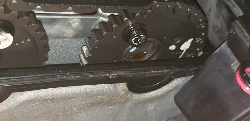
The factory marking on the exhaust side consists of 3 dots which line up with the top of the engine case. The intake marking is in a random location. There is no marking indicating which cam is which. I scored each gear with a metal scribe and marked the chain/gear match points in two places and labeled the exhaust and intake cam. 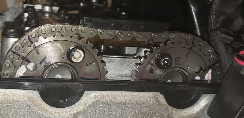
Rook your guide has been invaluable. Thanks for your hard work.
* Last updated by: LeapFrog on 6/2/2021 @ 4:09 PM *
cruderudy

Location: AMR
Joined: 08/15/12
Posts: 1963
Rook
Joined: 03/28/09
Posts: 20589
LeapFrog
Joined: 05/24/21
Posts: 2
Valve Clearance Check and Adjustment
07/08/21 2:26 PM
cruderudy
Here are my valve clearances at 30000 miles.
******Exhaust Exhaust Intake Intake
C#1 .180mm .180mm .148mm .148mm
C#2 .186mm .252mm .181mm .181mm
C#3 .246mm .178mm .142mm .142mm
C#4 .191mm .205mm .161mm .161mm
I installed the new shims, buckets, cams, and rechecked the clearances. Make sure you do this. The good clearance of .252mm on C#2 was zero clearance when I did the recheck. I must have moved the bucket enough to pull the shim out of it's pocket so it was sitting on the valve or pocket rim. This created a FAT shim condition. I had to remove the cams and reseat the shim. Got the bike put back together and it started. Miracles do happen!
* Last updated by: LeapFrog on 7/8/2021 @ 2:30 PM *
Rook
Joined: 03/28/09
Posts: 20589
New Post
Please login to post a response.