


LCD-200 Installation
The Dynojet LCD-200 is an onboard display used to monitor and log engine tuning data. The LCD receives the data from either a Power Commander 3 or Power Commander 5 so either of those devices must be installed to the bike before the LCD can function. The LCD firmware and cable are specific to the PC3 and the PCV so make sure the LCD you order is compatible to the fuel module you have. The LCD will also receive data from an in network Wideband 2 or AutoTune module. Some of the most commonly used functions and settings of the Power Commander 5, Wideband 2 and Autotune can be accessed through the LCD-200 rather than requiring a computer to be connected to the network. The LCD-200 need not be left on the vehicle permanently but Dynojet claims it is weatherproof.
Installation is a very simple procedure so use the instructions below how ever they suit the positioning of the Power Commander on your bike. The foam mount actually works quite well. It’s two drawbacks are that it prevents full lock righthand turns and the velcro grabs so hard that it pulls itself off the back of the LCD when you remove the unit from the bike. Also, it is not possible to access the memory card/USB port door which faces the side of the speedometer unless the LCD is removed from the mount.
The POD-300 is currently the latest and greatest in Dynojet real time engine parameter monitoring devices. This tutorial might be helpful for installing either device.
Do First:
-Install Power Commmander, see PCV Underseat Install
-Remove what ever is necessary to access your Power Commander and rout the LCD cable.
Seat
Ram Air Covers and Tank Cover Fairings, Gen1 Fairing Removal
Fuel Tank, steps 1 through 10 of Fuel Tank Removal
Tools:
zip ties
self adhesive zip tie mounts
one inch foam insulation
kitchen carving knife
foam insulation adhesive
60 grit sandpaper
black acrylic or latex paint
painters tape
double sided tape
self adhesive velcro
The LH side is the best option for wire connection fitment and one handed operation of the bike while operating the LCD.
1. Rout the small plug of the LCD cable under the fuel tank bracket to the power Commander. Rout the cable forward under the LH side frame to the back of the air box. 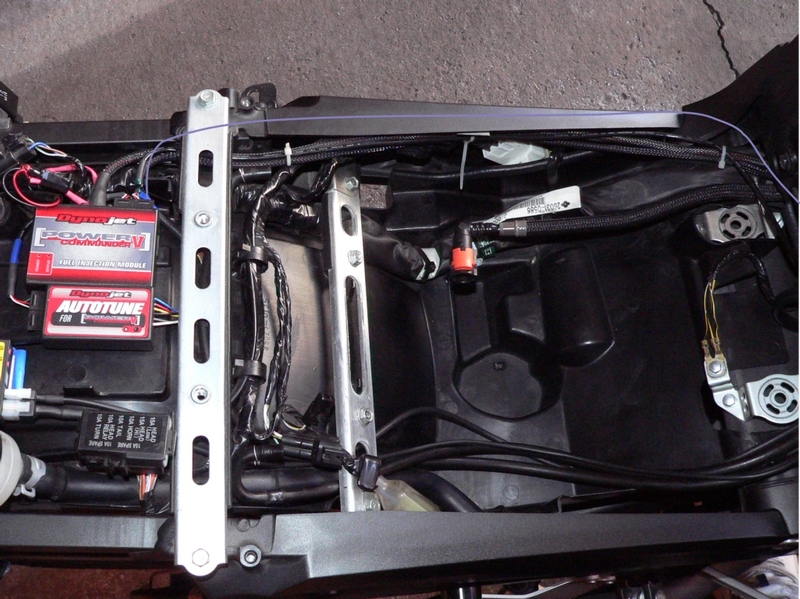
2. Rout the cable up the back center of the air box to the back of the steering neck and over to the LH ram air tube. 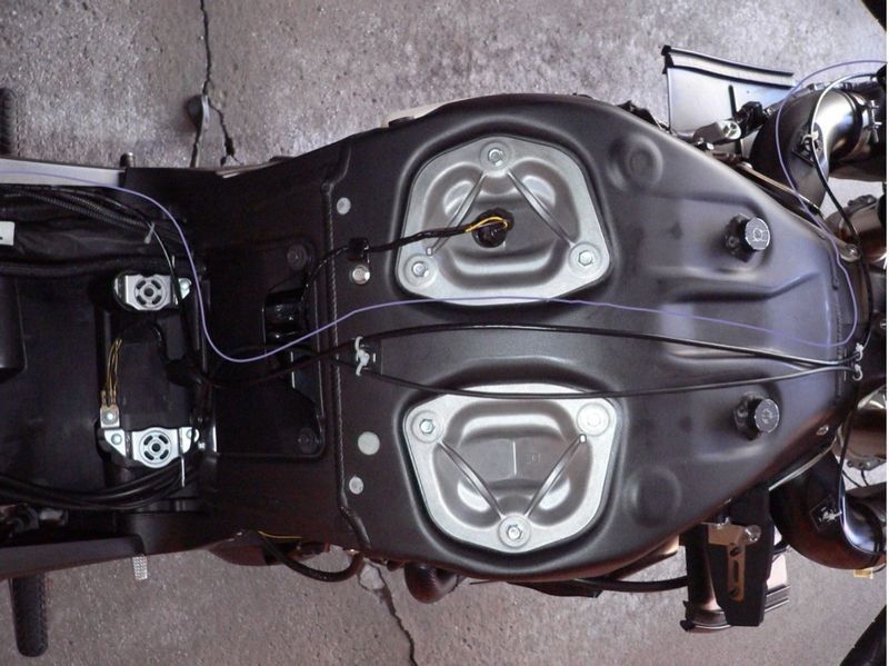
3. Rout the cable along the top of the LH ram air tube. Loosely fasten the cable to the ram air tube with zip ties and self adhesive zip tie mounts. Fasten the cable to the air box in the same way and loosely zip tie it to the Power Commander harness under the side frame.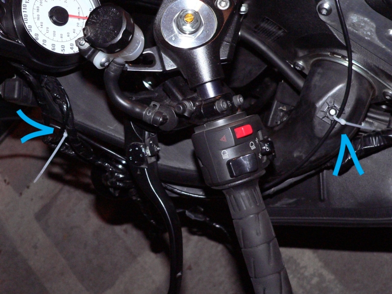
Remove the rubber terminator plug from any unused CAN port on the PCV and plug the LCD cable into the PCV.
4. Use the LH ram air tube cover as a template to trace the dimpled triangle shape onto a piece of one inch foam insulation. Roughly cut the triangle shape out with a kitchen carving knife.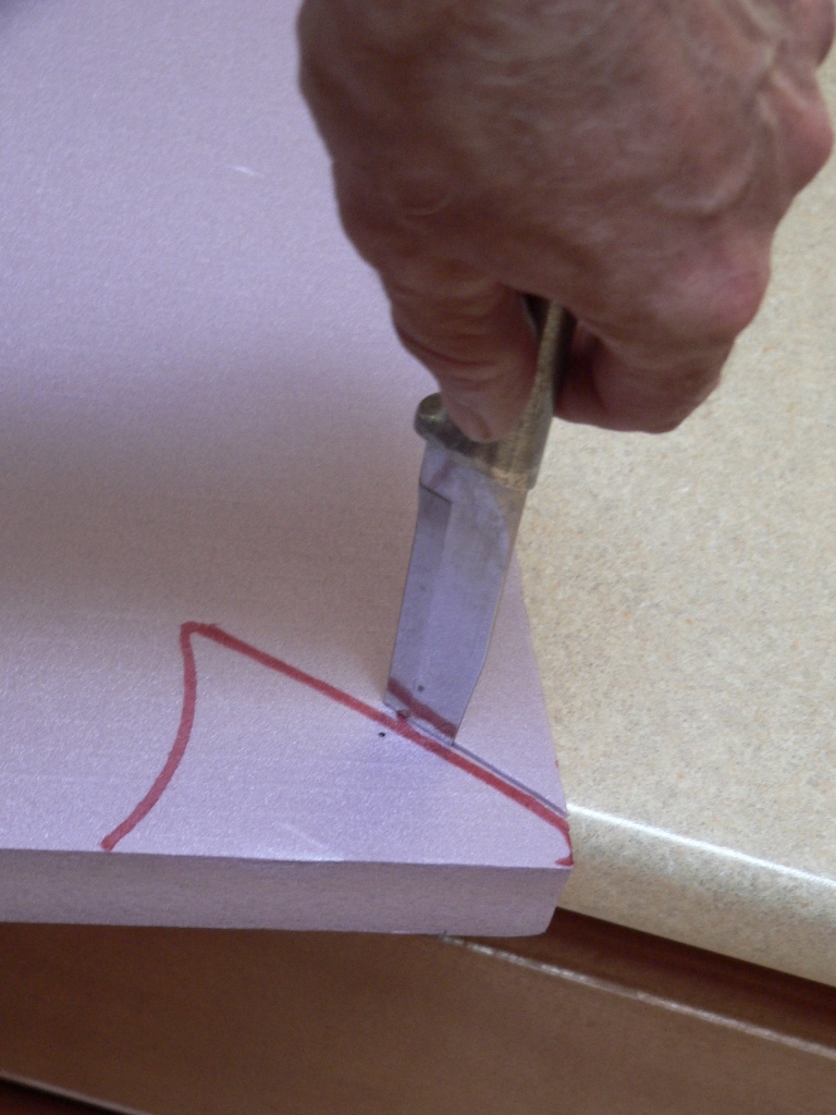
5. Trace and cut a second triangle shape from the foam insulation. You probably should make several of these in case there is an error in carving. Use foam insulation adhesive to adhere two pieces of foam together. You may roughen the surfaces with sandpaper and use wood glue but it will take several days to dry. Slice off thin layers to form a wedge shape that will slope inward toward the gage cluster. 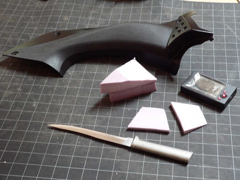
6. Use 60 grit sandpaper to perfect the shape and smooth the surface.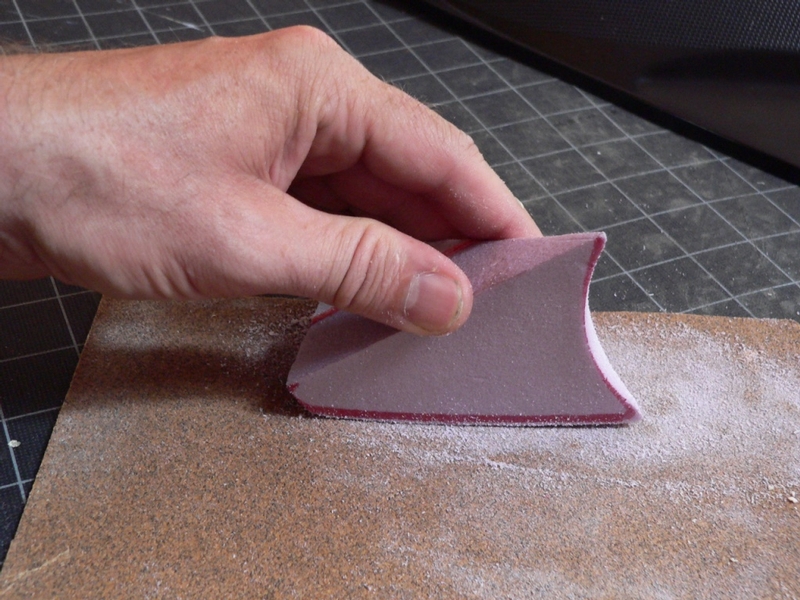
7. Use a rounded object covered with sandpaper to bevel the back of the foam slightly so that it fits perfectly against the triangle on the ram air cover. Also smooth the radius that adjoins the speedometer gauge.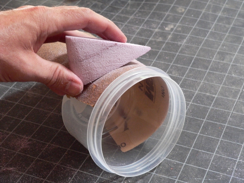
The finished piece will look something like this.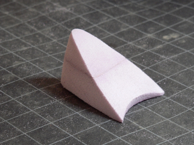
8. Paint the foam wedge black but DO NOT use anything but acrylic or latex paint. Solvents will dissolve the foam immediately. Apply blue painters tape to the triangle on the ram air tube cover neatly folding about one half inch over the edge. Tapping over the edge will keep the foam mounted much more securely to the cover than only taping the face. The painters tape has double sided tape adhered to it. Peel the plastic backing from the double sided tape and carefully stick the foam wedge to it.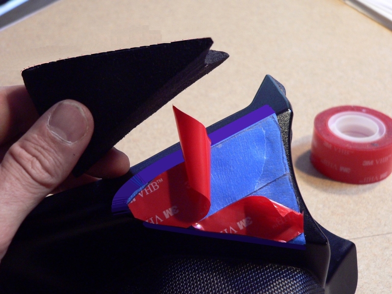
9. Install all removed parts allowing the large connector of the LCD cable to hang to the side of the foam mount.
Fuel Tank, steps 11 through 15 of Fuel Tank Removal
Ram Air Covers and Tank Cover Fairings, Gen1 Fairing Removal
Seat
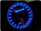
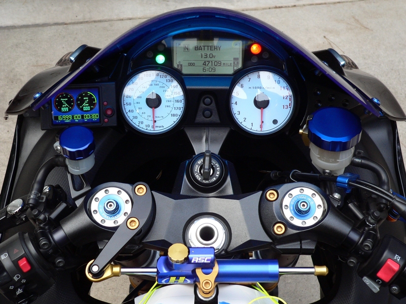
10. Place painters tape on the back of the LCD. The mount has both hook and eye strips of self adhesive velcro positioned on the face where the LCD mounts. Three 1/2 inch squares of velcro will be better than covering the entire surface as is shown in the picture. Peel the backing off the velcro and lightly touch the back of the LCD to the self adhesive. When you have the positioning you like you can press the LCD firmly against the self adhesive. There is not much leeway for positioning. Make sure the LCD cable and connector will not be obstructed.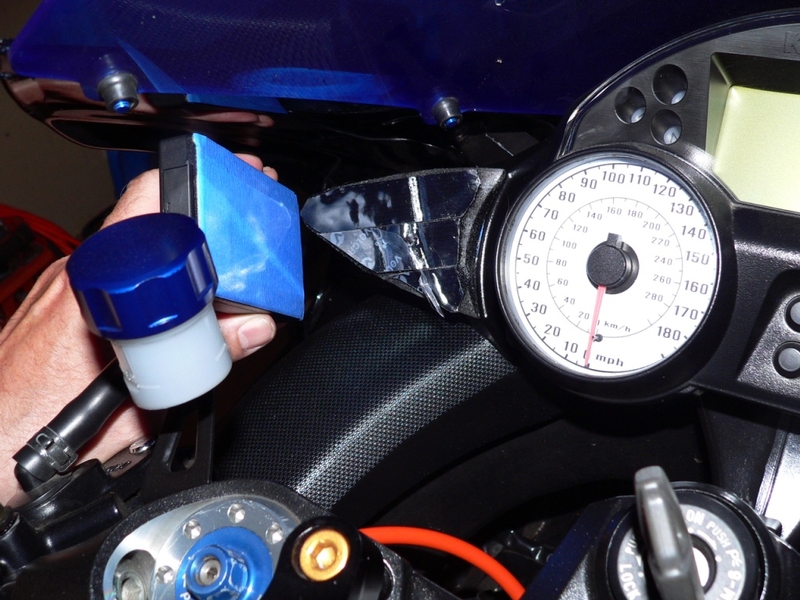
11. Hook the large locking connector up to its port on the LCD. It’s probably advisable to leave the LCD mounted for at least a few says so the self adhesive strips stick as firmly as possible. If the mount or LCD ever come loose, the locking cable connector will hold them from falling off. It's best to wait for the bike to cool off before sepparating the velcro to remove the LCD and also, hold the mount to the ram air tube so the double side tape is not loosened. If you run the bike without the LCD, the connector can be pushed behind he ram air cover with a plastic dust cover taped over it and perhaps a zip tie to secure the connector in reach.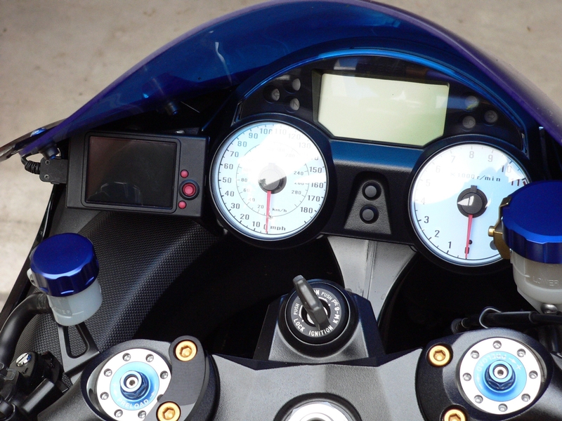
Weight:
The LCD with memory card and cable weigh 4.6 oz.
The foam mount and velcro weigh less than .5 oz.
Net weight gain about 5 oz
If you take the unit off leaving only the cable and mount, 2 oz weight gain.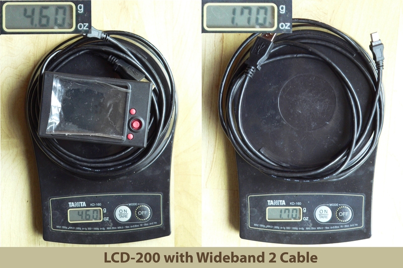
* Last updated by: Rook on 1/19/2018 @ 5:10 PM *