


Oil Gauges Install
Oil Pressure and Oil Temperature Gauges
An oil pressure gauge can be a life saver especially if the engine is subject to extreme running conditions. There is an OEM oil pressure switch but it only will trigger the oil light on the bike when oil pressure drops to a few psi which means it’s next to useless for anything but starting the bike. The oil switch can’t supply the proper signal to run an aftermarket gauge.
An oil temperature gauge is helpful to monitor the temperature of the engine oil which has an influence on oil pressure. The method of installing an oil temperature sensor I show in this tutorial will not produce adequate results to monitor oil temperature. I have installed it as shown but I will be changing my setup as soon as possible so I can get a useful reading off of the sensor.
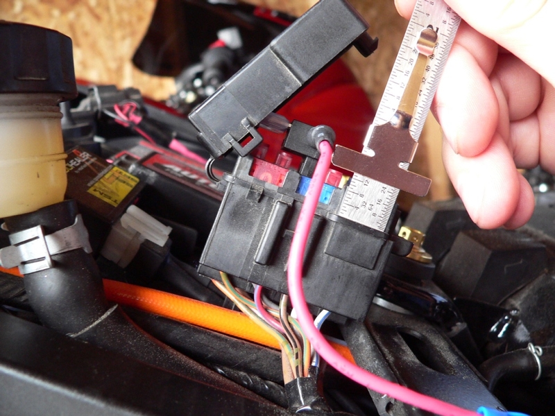
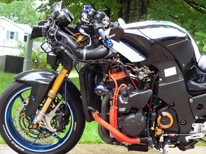
For a sport bike, the ZX-14 has a lot of extra dash space for additional gauges but it will be necessary to do some modification to the fairings to fit most gauges on the market. Check cup depth on the gauges you buy. A big part of the reason I chose GlowShift gauges was because they are only an inch and a half deep from the bezel to the back of the gauge. There are also very compact rectangular digital gauges available (check Dyno-Tune) that should be easy to fit almost anywhere you like.
Decide if you want analog or digital gauges. One big advantage to digital gauges is that their signal can be used to log data. Analog gauges are a lot easier to read at a glance but their signal cannot be data logged.
There are three ports that may be used to supply sensors for aftermarket oil temperature and or oil pressure gauges. An oil presser test port is located on each side of the engine case above the front lower fairing bracket. The oil switch boss to the LH side of the oil filter is the third location. If you wanted to create a sensor port instead of using an existing port, there is a blank hole directly above the oil switch. Another option for creating sensor ports is the oil filter sandwich adapter.
Sandwich Adapter
These adapters sandwich between the oil filter seat and the oil filter. They are designed to provide a quick and easy source of flowing oil. I would recommend that this avenue be taken as the easiest by far. I have not tried a sandwich adapter but I’m sure one for the ZX-14 could be found without much investigation. Gauge manufactures often sell sandwich adapters that work with their gauges but you might consider using an inexpensive sandwich adapter from Asia. As long as it seals between the oil filter and seat and has 1/8 NPT ports, it will work. The downsides to a sandwich adapter are that it would add a reasonable amount of weight, locate the oil filter an inch farther forward (although there is plenty of space) and the space constraints of the ZX-14 require that the oil sensors be pointed down. Downward pointing sensors will protrude slightly from the fairing and be vulnerable to damage from flying road debris. I have heard one report that temperature sensors do not work very well with sandwich adapters because the probe is not fully immersed in the flow of oil. Still, a sandwich adapter would give you oil ports with as little effort as removing the oil filter. It is by far the most plug and play method of acquiring an oil source for your gauges and it will cost less than buying a multi port adapter and tools.
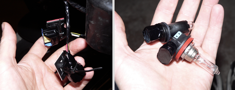
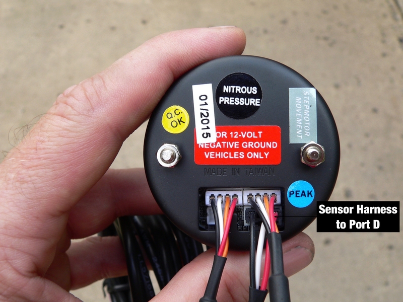
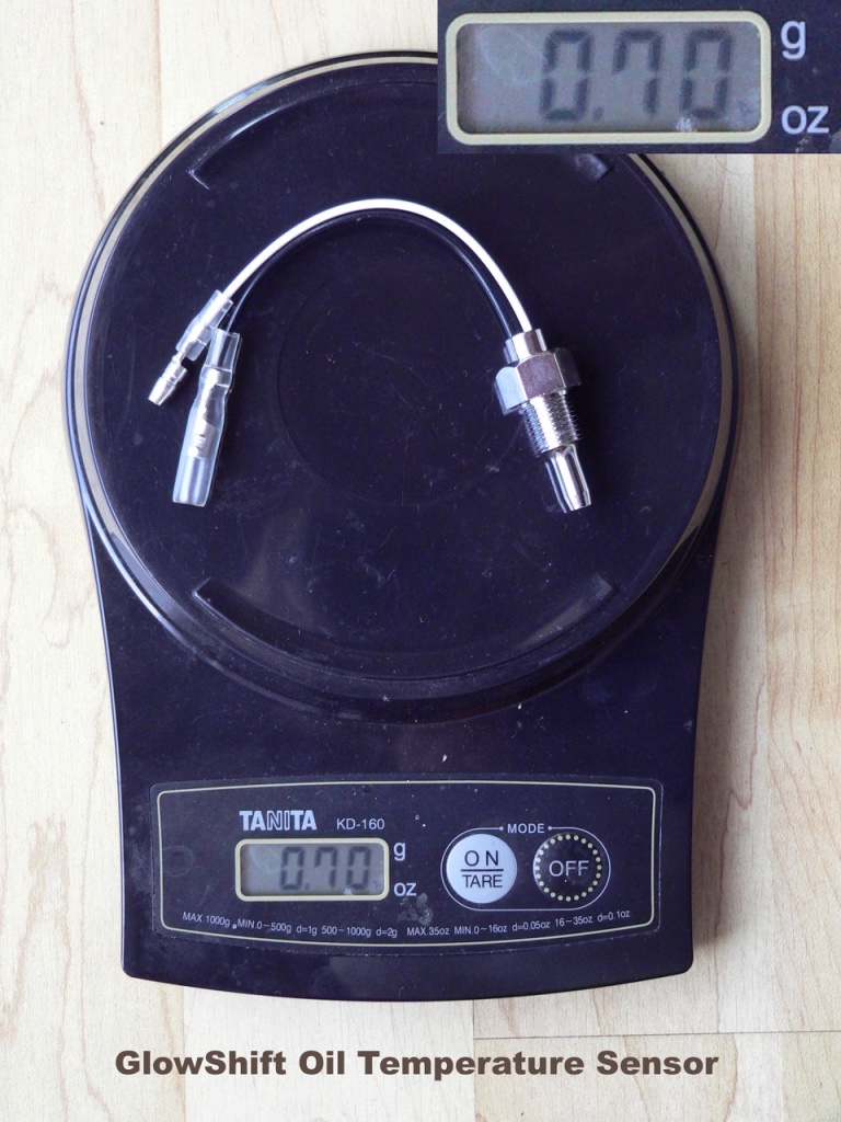
All brands of gauges will have similar sensors to those shown in this tutorial. Provided it has 1/8 NPT thread (which is the most common thread for automotive and motorcycle sensor bosses) the sensor can be installed exactly the same way as is show in this tutorial.
Oil Pressure Test Ports
Either of the oil pressure test ports located at each end of the crankshaft may be used but there is not enough room between the engine case and the inside of the lower fairing to mount a sensor there. A sensor could be installed to a union at the end of a copper tube with a pressure coupling installed in an oil pressure test port. The tube could be easily bent to position the sensor where it would not interfere with the fairing. Similarly, an elbow with a steel braided line would permit remote location of an oil pressure sensor. Neither would work well for an oil temperature sensor. The oil temperature in the line would not reflect the temperature of the oil in the motor because the oil would be more or less stagnant. Without having the oil flowing through the line as it does in the engine, the sensor would not be exposed to the same oil temperature as the oil currently circulating in the engine. Also, the oil would not be likely to ever reach the peak temperature that the oil in the engine does because the line is located outside of the engine. Another undesirable aspect of using an oil test port is the risk of thread damage. The LH oil pressure test port is located in the oil pan so repairing damaged threads would be relatively uncomplicated. The oil pressure test port on the RH side is located in the engine case so major engine disassembly would probably be required to repair threads there.
Auxiliary Oil Sensor Blank
There is a well located in the oil pan approximately one inch above the oil pressure switch and it already has a center detent to pilot a drill bit. It seems this location was meant to be drilled and threaded to provide an oil supply. As far as I can tell, the resulting passage would intersect with the passage immediately after the oil pressure switch. The oil pressure switch would not need to be relocated and the threads for the auxiliary oil sensor hole could be cut to fit whatever adapter or sensor one wished. The complication is that drilling and tapping threads here would entail removing the oil pan and irreversibly altering a fairly expensive OEM part.
Oil Pressure Switch Boss
Other than a sandwich adapter, this is probably the most straightforward method of acquiring ports for oil sending units. It requires installing a multi-port adapter but there is enough room for multiple sensors. If any damage should occur from the installation of an adapter, the oil pan could be removed for repair or replacement. The disadvantages to using the oil pressure switch boss is that you must relocate the oil pressure switch (if you want to have a functioning low oil pressure warning light) and a multi-port adapter will not have much oil circulation to monitor oil temperature. An oil temperature sensor in an adapter located right off of the engine will not rise very much above 140° F. Another problem with using the oil pressure switch boss is that the multi-port adapter will probably need to modified so its threads fit the port in the boss (see Multi-port Oil Sending Unit Adapter Mod).
I chose to use a multi-port adapter installed to the oil switch boss as the best longterm solution for locating oil sending units. I am quite certain I will use the auxiliary oil sensor blank for the temperature sensor in the future because of the constant oil flow but the multi-port adapter in the oil switch boss will still be handy if I ever need oil supply for turbo.
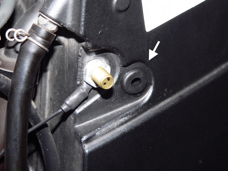
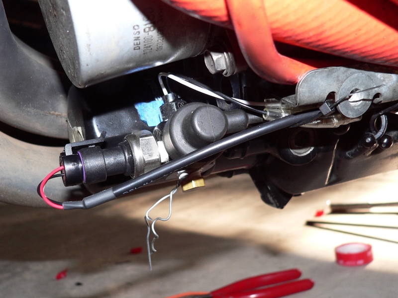
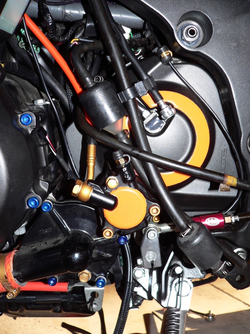
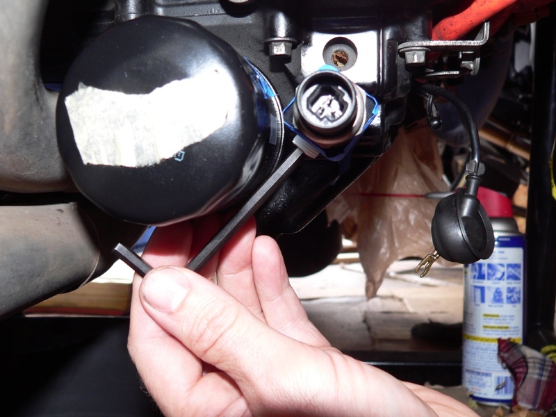
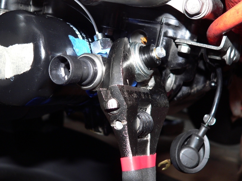
RH oil pressure test port.
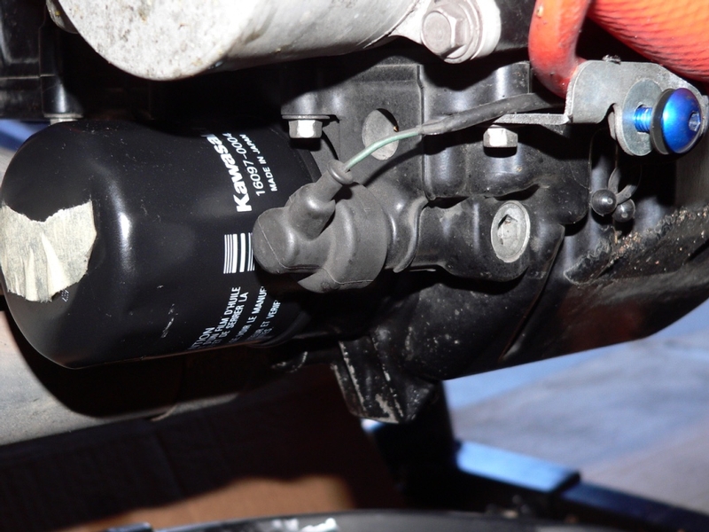
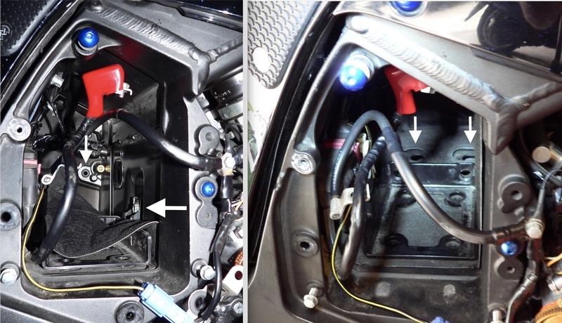
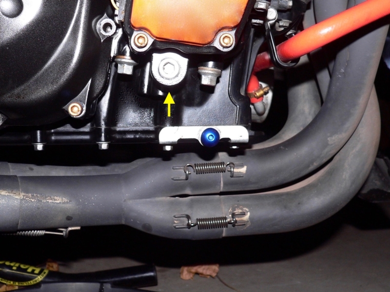
This photo shows the oil pressure switch installed as well as the LH oil pressure test port around the corner and the auxiliary oil sensor blank above.
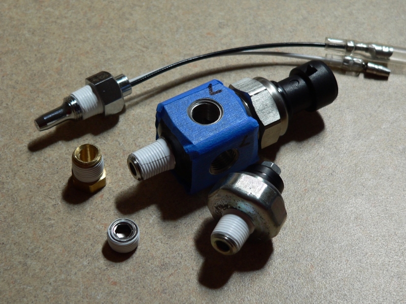
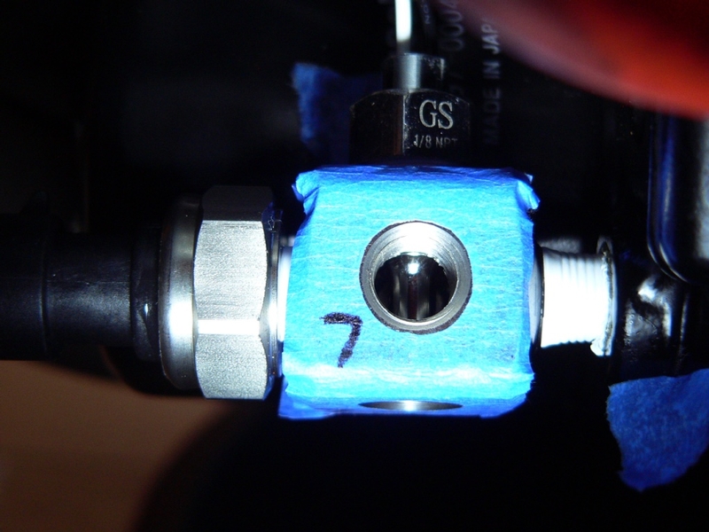
All three of the sensors I am installing to the adapter I have are a little smaller in thread diameter than is typical for 1/8 NPT fittings. The sensors should be threaded in finger tight and then one and a half to three complete 360° turns to seal. I did a careful examination of the number of female threads within each adapter port and the male threads after the sensors were finger tight. There were only about two threads available on each sensor for final tightening. Further, the crests and roots of the threads in the front female port have been flattened, apparently to fit better with rolled threads. I do not know if rolled threads are a plus when mated to the more common cut threads. The rolling process has made the thread diameter in the front port even larger which means fittings must thread in deeper to tighten.
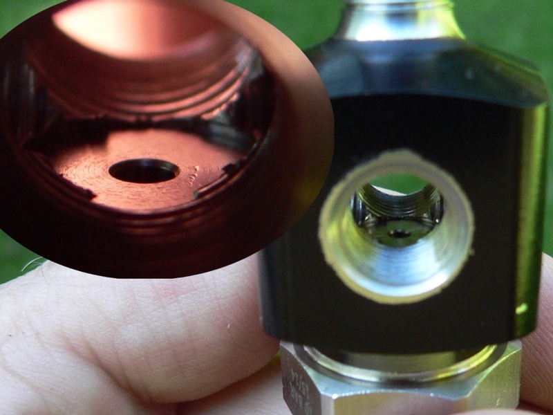
The front port in the adapter where the oil pressure sensor will be installed has four projections at the bottom because the threads were not cut clean through to the center. A sensor with a smaller thread diameter might bottom out on the projections before the threads seal against one another.
The front adapter port is also 1/8 BSPT which is a slightly different thread than the 1/8 NPT oil pressure sensor (see NPT v BSPT in the introduction of MULTI-PORT ADAPTER TO OIL SWITCH BOSS MOD). 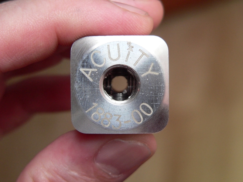
Brand of Gauges
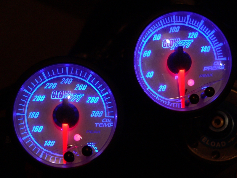
This tutorial details GlowShift oil gauges installation but much of it will be helpful for the installation of any brand of oil gauges. I can neither recommend nor discourage the use of GlowShift gauges. They are compact for a traditional cup gauge, they look great, they do work and they are relatively inexpensive. The brand of choice depends on the priorities of the individual who will be using the gauges, however. Check out my review of Glowshift gauges on the link in the list below.
Let me mention one more time, NO oil temperature sensor will do much installed in an adapter. It won’t indicate much above 140° F.
Helpful Info
OIL PRESSURE ENHANCEMENT
GLOWSHIFT GAUGES PRODUCT REVIEW
Engine without oil for extended period
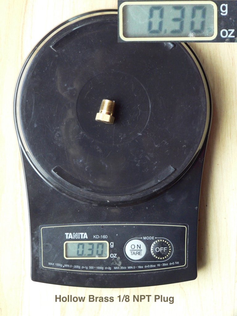
If you do use brass even though I think it’s a horrible idea for this…
Do First:
Remove the battery (BATTERY REMOVAL, steps 1 through 4).
Remove the stock oil pressure sensor (see OIL PRESSURE SENSOR REMOVAL, steps 1 through 5)
Determine if your multi-port oil sensor adapter threads fit the oil switch boss and modify it if necessary (see Multi-Port Oil Sending Unit Adapter Mod).
OR —use one of the other aforementioned options for an oil sending unit source.
Tools:
multi-port oil sensor adapter
mineral spirits
masking tape
X-acto knife.
VHT semi-gloss black engine enamel
safety pin
small sewing needle
compressed air
medium density heavy-duty PTFE tape
vice
adjustable wrench
painters tape
torque wrench
standard allen wrench
14mm open end wrench
handlebar accessory brackets
Goop
6 mm wrench
nonpermanent thread locking agent
vinyl
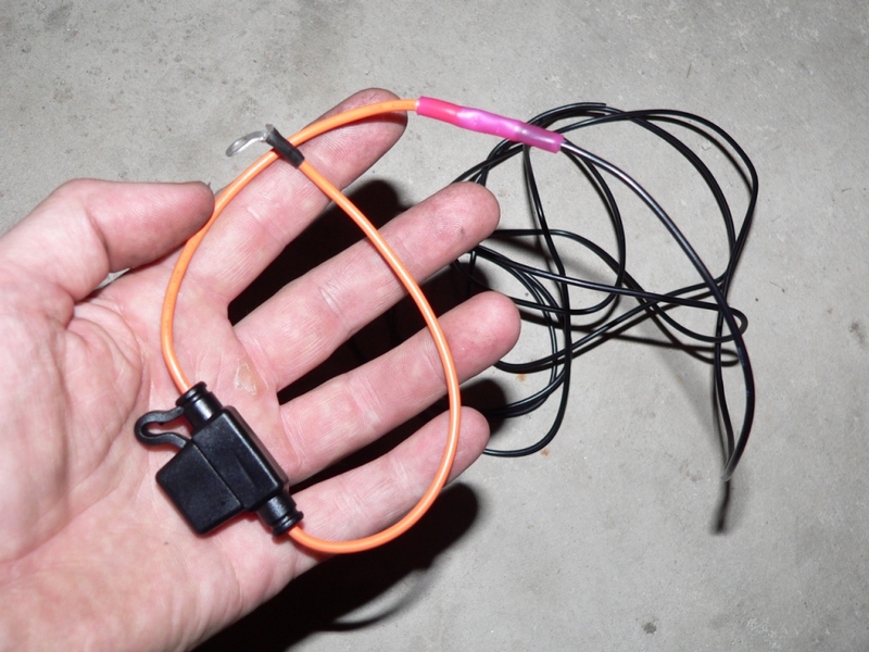
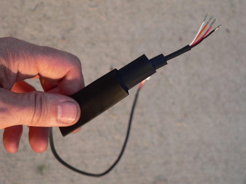
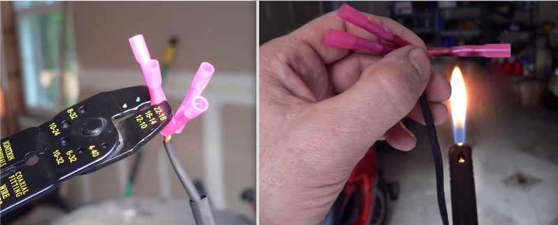
shrink tube
Two or three 3 to 5 amp fuses
posi-taps (optional)
crimping tool
ring terminal
RTV silicone sealant
18 gauge weather proof butt connects
18 gauge wire
quarter inch, half inch or eighth inch grommet.
medium-duty double sided tape
1/8” and 1/4” PET sleeving
zip ties, 14” and 4”
P-clip (optional)
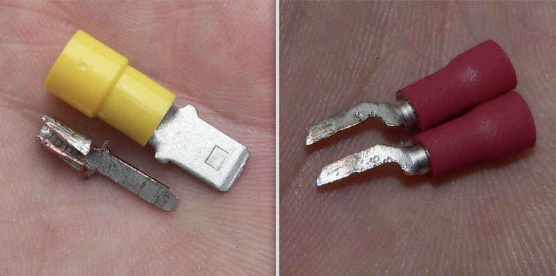
7/64” female contact for 22-18 gauge wire (audio contacts)
small steel rod
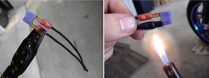
lighter
file 3/16”
1/4” male contacts for 12-10 gauge wire
Sharpie
electrical tape
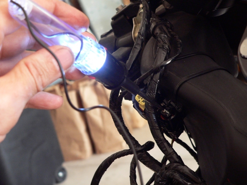
test light
Multi-Port Sending Unit Adapter and Sensors
1. Because it will be very close to the vent hole in the lower cowl, you may want to paint the multi-port oil sensor adapter so it is less conspicuous when installed.
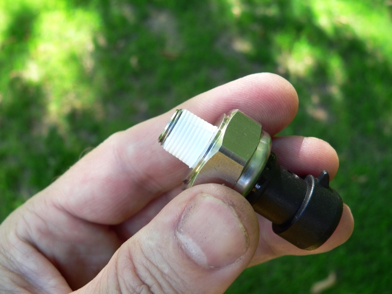
Wash the adapter with mineral spirits.
Mask off the threads on the male port and mask an area around each female port so no paint can seep into the threads. I traced the circle shaped masks and cut them with an X-acto knife.
2. I tried Duplicolor self-etching primer without scuff sanding the surface. The primer peeled right off when I removed the tape as though the paint film was not adhered at all. A light coat of VHT semi-gloss black engine enamel on unprepared metal sticks much better.
Allow the paint to cure overnight.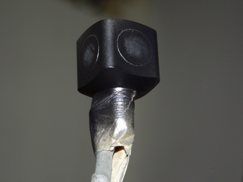
3. Test fit the multi-port oil sensor adapter finger tight in the oil switch boss.
The multi-port oil sensor adapter needs to be positioned so that all female ports are facing the direction(s) that will allow clearance between the sensors, the oil filter, oil cooler and the fairing. It’s less desirable to have any sensors facing downward where they are more vulnerable to flying road debris.
Loosely install all sensors in their proper port.
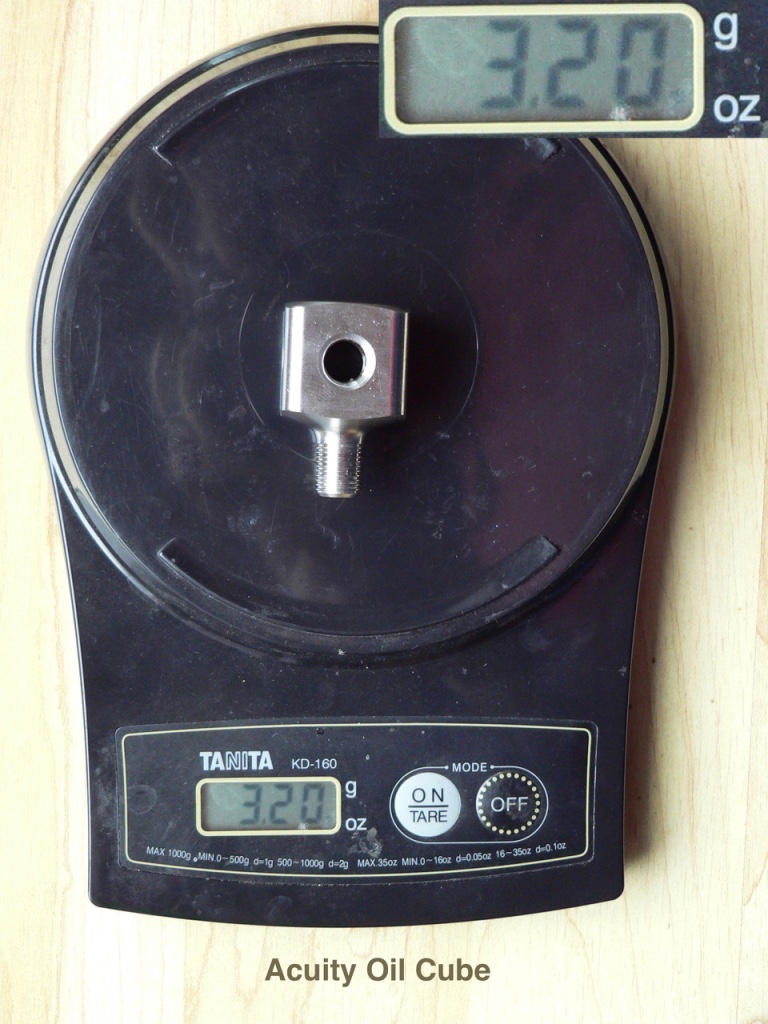
You can mark the Acuity adapter according to what sensor goes to each port and be fairly certain this will match the orientation after the adapter is installed.
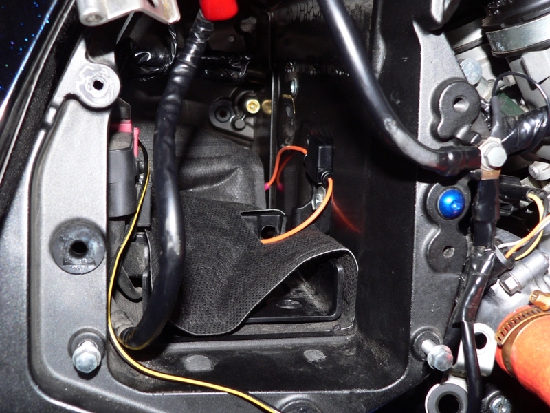
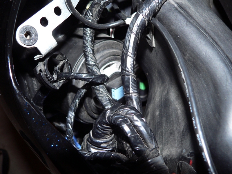
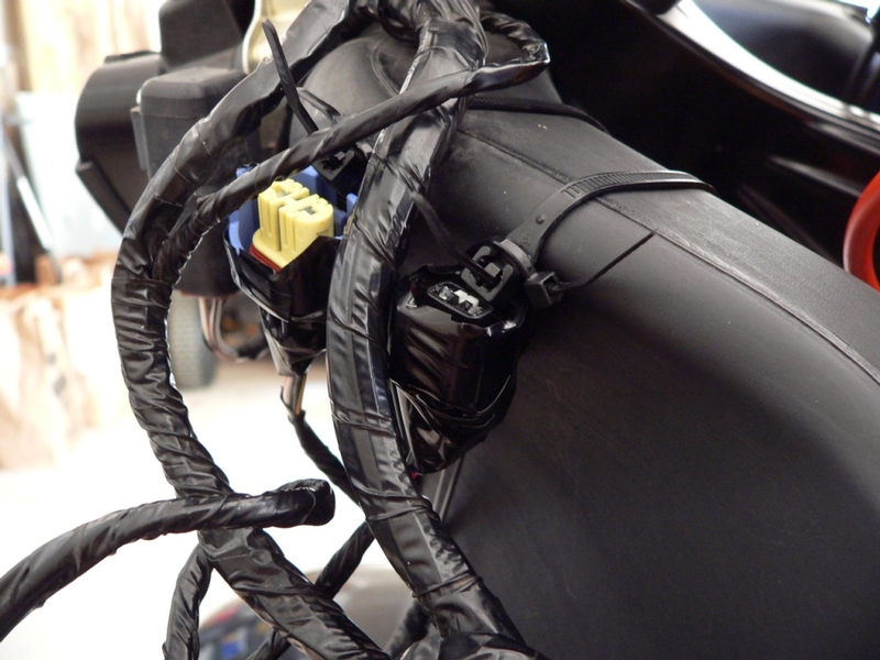
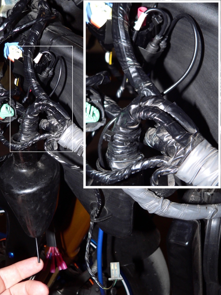
Be sure that the oil pressure switch wire will reach the terminal. I rerouted the wire under the front LH lower fairing bracket.
Install the LH lower fairing to check clearance with the test fit and aesthetic preference for the oil switch location. There is really not much of a choice. I found turning the top point to approximately one o’clock to be the best balance between making the oil switch least conspicuous and making the top RH port of the oil Cube accessible.
Remove the LH lower fairing, multi-port oil sensor adapter and all sensors.
4. If any sensors have a factory installed coating of solid thread sealant, I would suggest you block the hole in the sensor and remove the sealant with a needle. The solid sealant seems like a definite engine contamination hazard if the sensor is threaded into the port deep enough to protrude inside the adapter or if the sensor needs to be removed.
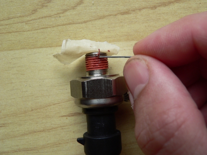
I ran a safety pin through the threads first and then blew the fragments away with compressed air. I then carefully scraped away at the remaining sealant with a small sewing needle blowing the threads clean four or five times. It is not possible to remove every trace of sealant.
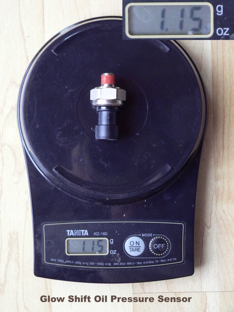
5. The Glow Shift oil pressure sensor is small enough in diameter to bottom out on the projections at the bottom of the front port of the Acuity adapter. I decided to install the oil pressure sensor to the adapter before the adapter was installed to the oil switch boss so I could monitor that situation more closely. If the adapter you are using is hexagonal and has a clear front port, you may want to install the adapter to the oil switch boss first so that you can use a socket and torque wrench on it.
Use 2 wraps of medium density heavy-duty PTFE tape on the sensor threads from top to bottom. Wrap the tape clockwise as you look at the hole in the sensor so the trailing end flows with the direction of tightening. If the tape is wound the opposite direction, it will fold back and bunch up as the sensor is tightened.
Slice off the excess PTFE with an X-acto knife so the first two threads are bare. Do not allow any PTFE to extend beyond the last thread of the fitting or it will almost definitely break off, possibly causing an oil flow problem in the engine.
Medium density teflon tape is about 3 times the thickness of the average light duty teflon tape I have used. Medium density is much easier to work with and the heavy-duty variety is rated to withstand 550° F and 300 psi. It is also under two dollars a roll so I suggest you pick some up at an industrial supply company such as Fastenal. After test fitting with regular low density teflon tape that is more common, I would be a little hesitant to use it for this application.
Although it’s often said teflon tape is designed to be a thread lubricant more than a sealant, many people claim it works great for sealing less than reliable pipe joints. It may not be as permanent as a high temp liquid sealant and it may present a slightly higher contamination risk if the fitting is removed. I chose to use it because:
A) it may be the most effective thing to fill in the pitch difference between the front female BSPT port and the oil pressure sensor’s male NPT port.
B) it will help take up the difference between the atypically small thread diameter on my sensors and the average sized female thread diameter of the adapter ports.
C) will cause less wear on the the female threads if the sensors malfunction from heat or vibration and need be replaced or repositioned.
D) will allow for additional tightening without breaking the entire existing seal if there is a leak.
In short, teflon tape will work, is best for temporary installation and just might last forever.
I suggest NOT using both liquid thread sealant and teflon tape. That could make removal of the sensor extremely difficult and it might be a huge engine contamination risk. I would only consider it if I knew the installation was going to be permanent (which at this point, I do not).
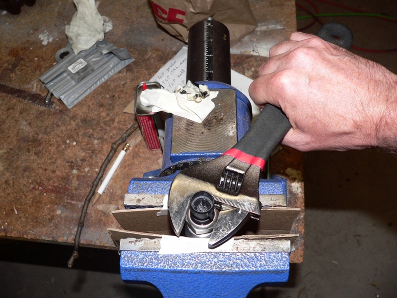
6. Place the multi port adapter in a vice.
Tighten the oil pressure sensor with teflon tape applied to its threads into the front port of the adapter as tight as you can by hand.
Tighten the sensor with a wrench.
There is no definite rule on how tight a fitting should be to cause it to seal. Generally, the grunt twice rule is applied. Tighten until the fitting is “good and tight” (grunt #1) and then tighten a nudge tighter (grunt #2).
PTFE tape is a powerful lubricant so fittings will tighten more smoothly than they do with liquid sealant. Use judgement if you use PTFE because over-tightening can cause leaks as well as thread damage. In this case, we have limited threads before the sensor butts into the cross ports so that will be the deciding factor.
I tightened the Glow Shift oil pressure sensor into the female port of the Acuity oil cube one and three-quarters turns past max hand tight. I would estimate this required less than 10 ft lbs of torque. The threads glided together the whole way. I stopped turning as soon as I thought I felt the slightest resistance. It is very possible that I came to the end of the female threads or the inconsistency of threads per inch between 1/8 NPT and 1/8 BSPT reached it’s limit. Tightening any more would be out of the question anyway because the male port is about to enter the ports for other sensors which will likely thread in deep enough to cross its path.
7. Have a close look at the other female ports in you multi-port adapter. Count the number of valleys in the threads above the intersecting ports to determine the maximum depth a fitting can be threaded in. The Acuity adapter has 7 to 8 threads above the intersecting ports which means a fitting should be threaded in no more than seven 360° turns (or somewhat less to be safe).
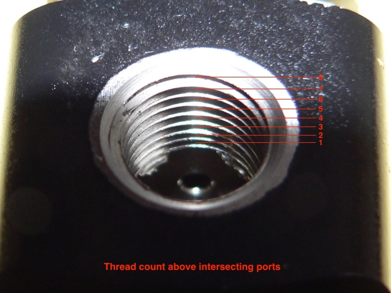
Avoid tightening any fitting so much that it protrudes into other ports. It would be OK if one fitting protruded into the cross ports but that would prevent any other fitting from being tightened past the depth of its port.
8. Next, thread each fitting finger tight into its adapter port. Determine how many threads deep the fitting will go when tightened with a wrench. Wrench tight is finger tight plus 2 or 3 more turns.
If it appears that the fitting will protrude into the other ports or that the top will contact the outside surface of the adapter when the fitting is tightened, the fitting’s thread diameter is too small. You will have an idea of how much PTFE to use.
9. Cut holes in painters tape for the female ports and wrap it around the adapter to help protect the paint from being scraped. If any paint comes loose during installation, it will stick to the tape.
Apply medium density high temperature PTFE to all fittings that require a tighter fit. In the event that you need to remove any fitting in the near future, I think PTFE would be the easiest sealant to clean up. It also may be tightened up a bit later if the fitting does not seal.
Make sure that no PTFE can enter the port beyond the bottom thread or it will break off inside the multi-port adapter and contaminate the engine.
The Glow Shift temperature sensor has such small threads that there are only two threads left to tighten it after it is threaded in finger tight. The top of the sensor might contact the port after it is tightened with a wrench. I applied 5 wraps of medium density PTFE and cut the PTFE off of the bottom 3 threads. If any of the sensors need to tightened far enough to protrude into the cross ports, it will be this one.
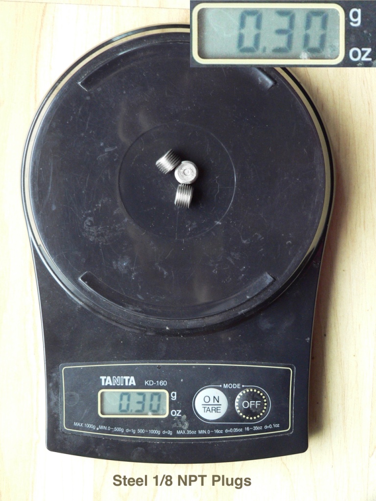
I cleaned the oil switch threads with mineral spirits before applying three wraps of PTFE. The plugs each received two wraps of PTFE.
10. Install the multi-port sensor adapter to the oil pressure switch port in the oil pan (follow steps 7 through 10, Oil Pressure Switch Removal).
If the multi-port sensor adapter you are using is not equipped with a hex (the Acuity Oil Cube has no hex), set a torque wrench to 11 foot lbs and place it onto an engine mount. Clicking the torque wrench at the 11 foot lb. setting will help you judge the proper torque for the oil cube. You may need to go lighter on tightening to get the ports aligned how you want them. Do not over-torque the adapter to get the ports positioned properly. If you’re using PTFE, you probably want to go for more like 8 ft lbs or less.
OR—
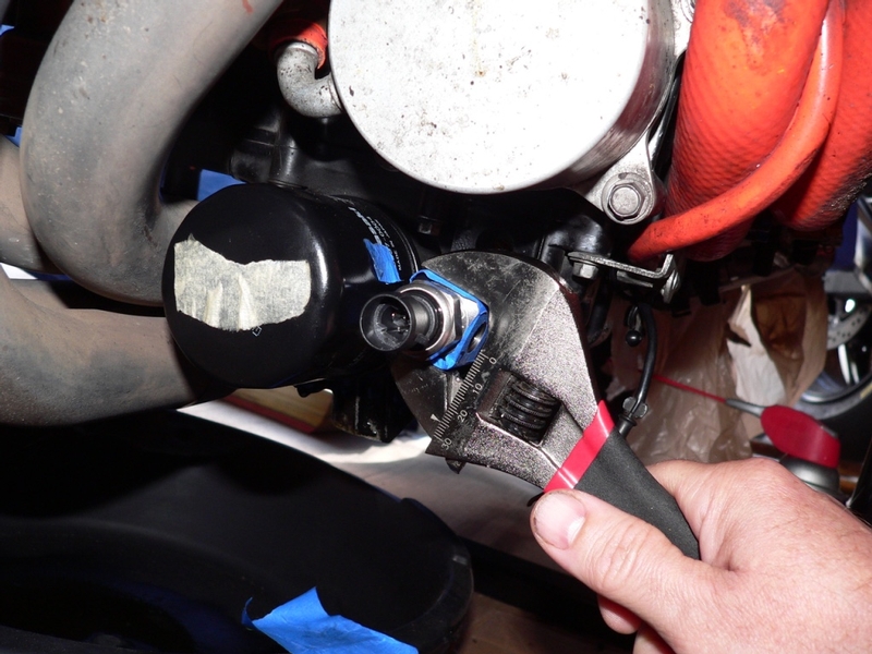
Use an adjustable wrench to tighten the body of the multi-port oil sending unit adapter.
If there is a plug that needs to be installed next to the oil filter, allow room for a wrench before tightening of the adapter to the desired position (see step 11 below).
The Acuity Oil Cube threaded in 3 turns finger tight and then two more turns with a wrench. This felt less than the 11 foot lb torque spec but it was 5 threads deep which was the same depth that the oil pressure switch was installed by the factory.
DO NOT OVER-TIGHTEN THE ADAPTER—THE OIL PRESSURE SWITCH BOSS CAN CRACK, INCREASED THREAD WARE OR A FAULTY SEAL MAY OCCUR FROM OVER-TIGHTENING.
11. Install any plugs on the side of the adapter that faces the oil filter, then tighten the adapter to the desired position.
I tightened one steel plug that came with the Acuity adapter about two turns past finger tight. It was a standard Allen wrench, not metric.
12. Use a 14mm open end wrench to tighten the Glow-Shift temperature sensor.
I tightened the Glow-Shift temperature sensor until I could see the first thread entering the adjacent port. It can be tightened more if it leaks.
I tightened the oil pressure switch about six and a half turns (lost count because I was interrupted). It felt like 10 ft lbs even with the three wraps of tape on the threads. Might have felt it stop against the oil temp sensor threads.
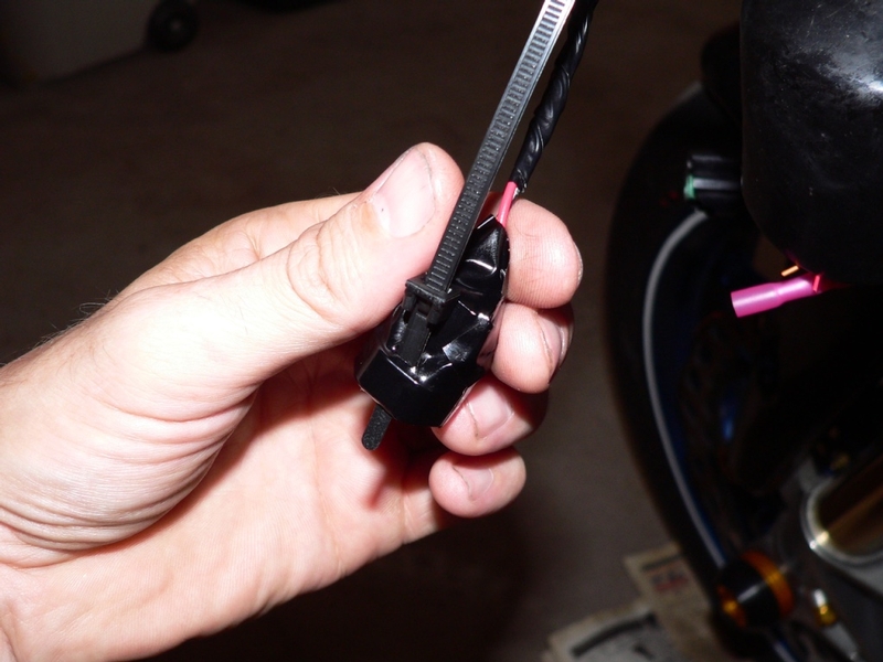
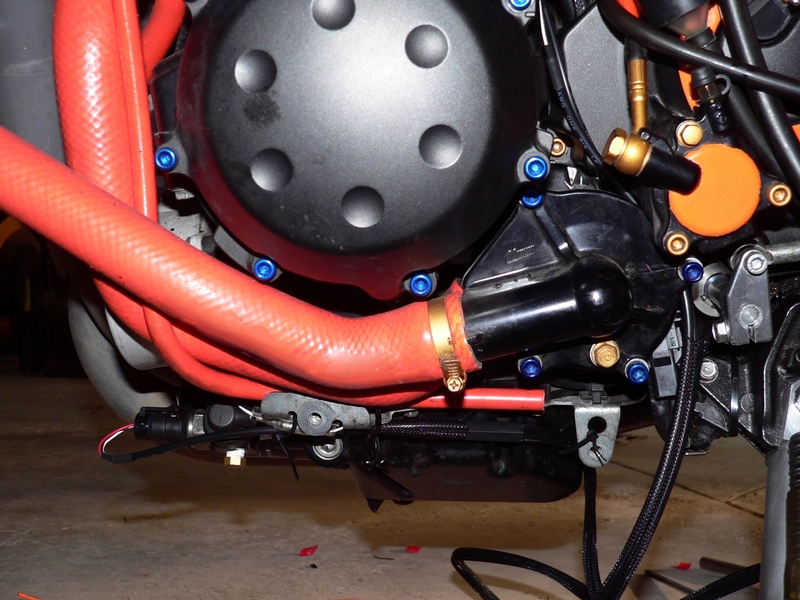
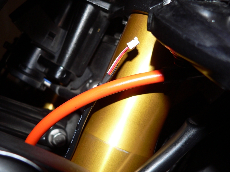
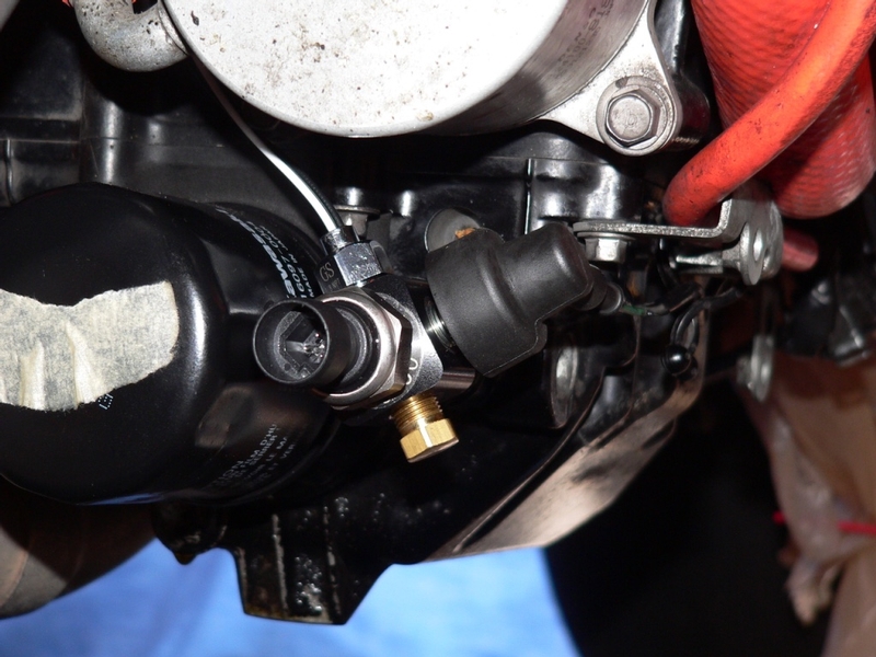
13. Rout the oil pressure switch wire safely, connect the oil pressure switch terminal and put the rubber cover over the oil pressure switch (see Oil Pressure Switch Removal, steps 11 through 13).
I rerouted the oil pressure switch wire under the front lower fairing bracket. It is fastened by the stock plastic clip.
14. Fill the crankcase with oil (OIL CHANGE, steps 5 through 7).
Connect the battery negative cable (see Battery Removal, step 5)
Prime the oil pump if you wish (see step 13, Oil Pressure Switch Removal.
Start the engine and observe for leaks at the oil sensor adapter and the sensors. Use a rag to test for drips.
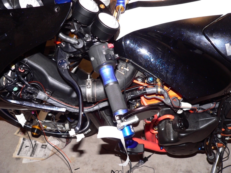
Gauges
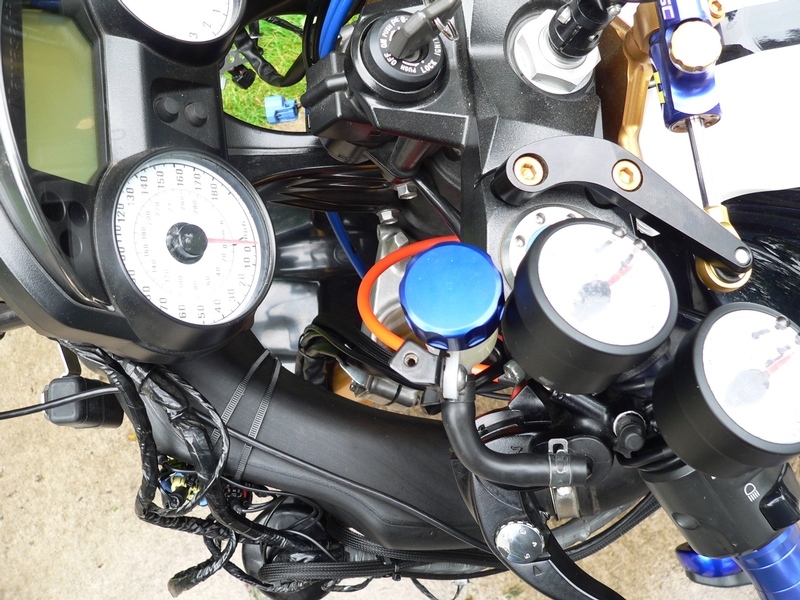
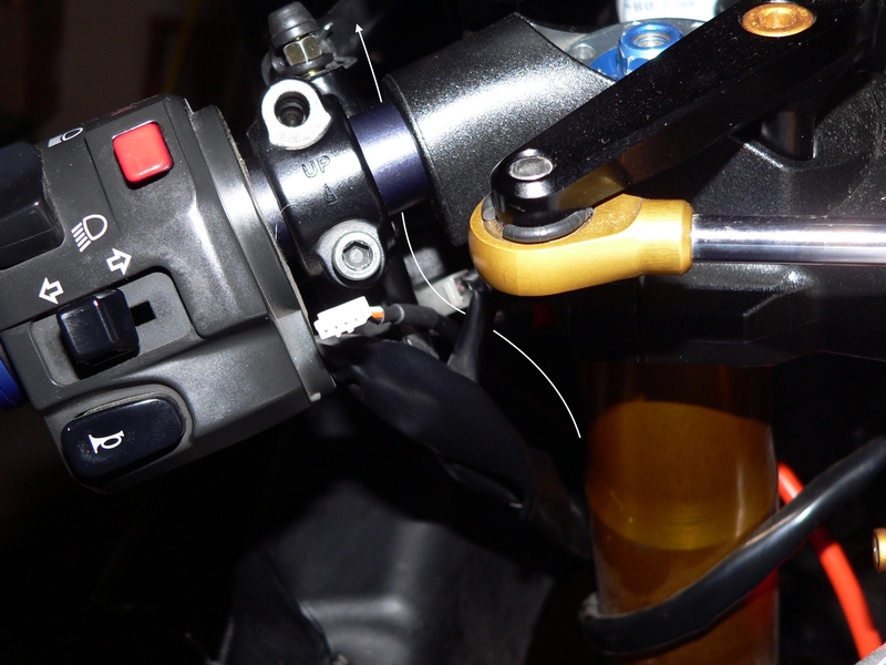
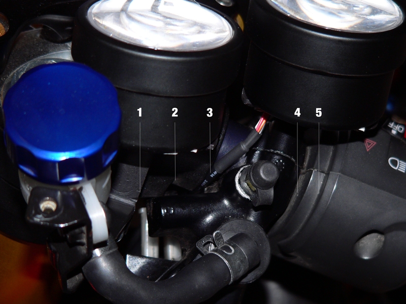
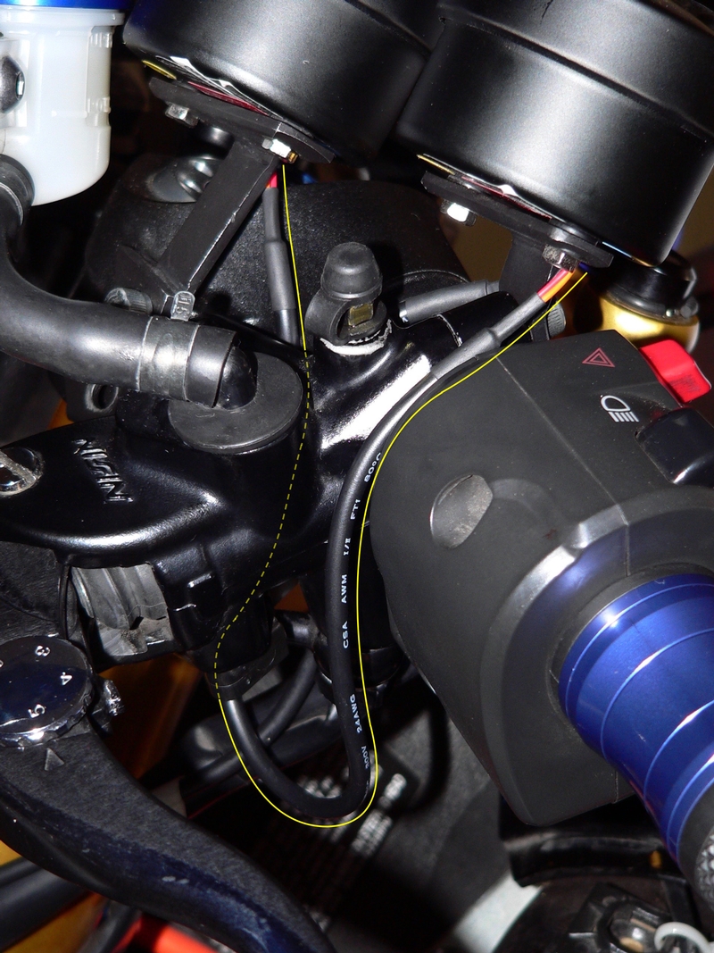
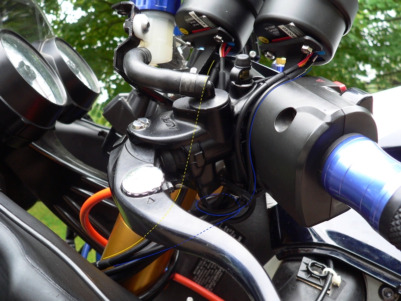
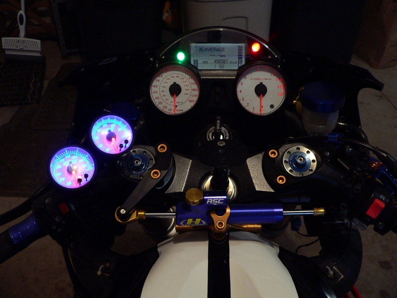
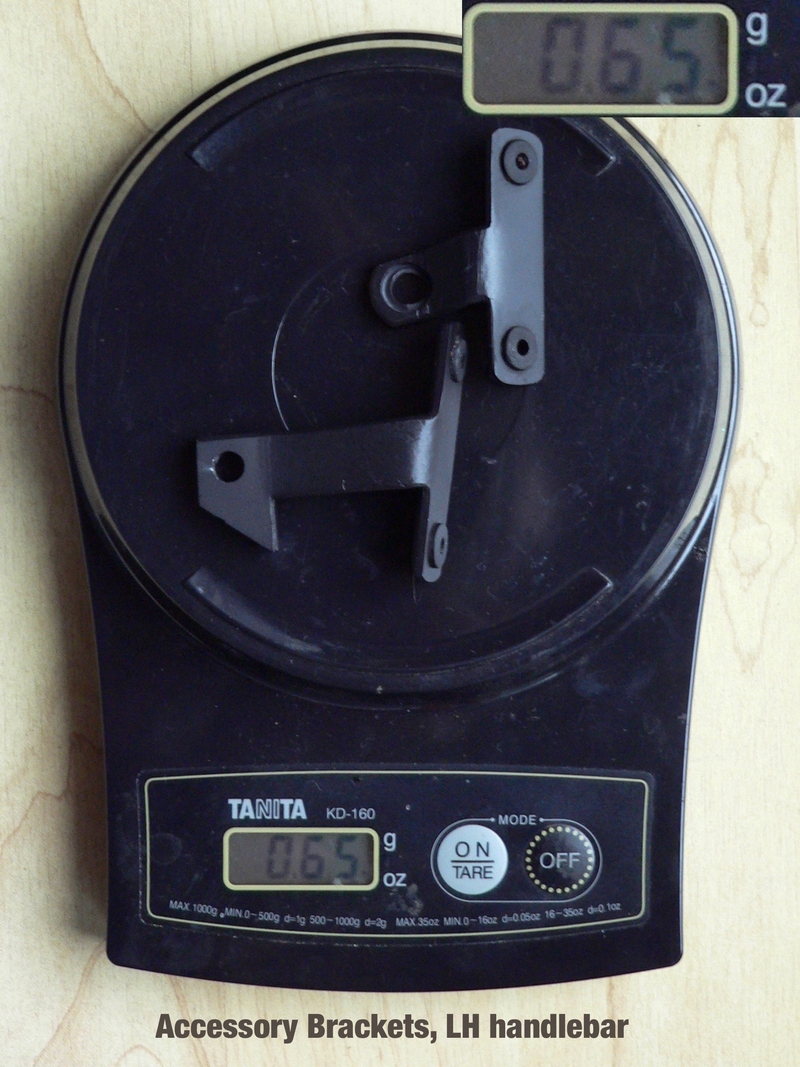
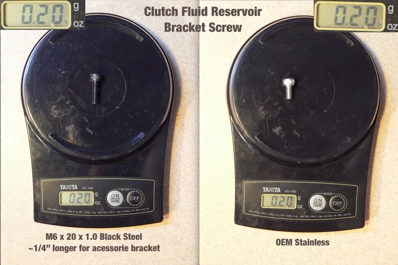
Mounting the gauges to the handlebars will probably be the easiest way to do it. I made aluminum brackets that fasten to the master cylinder clamps and fluid reservoir bracket mount. There is very little space to spare near the clutch fluid reservoir and the front brake fluid reservoir definitely would need to be repositioned to fit a gauge in a similar fashion on the RH handlebar. My bracket moves the reservoir forward 1/4” which stresses the rubber hose just a bit. Mounting the gauges close together and close to the handlebars makes the most sense but this also results in very tight clearances.
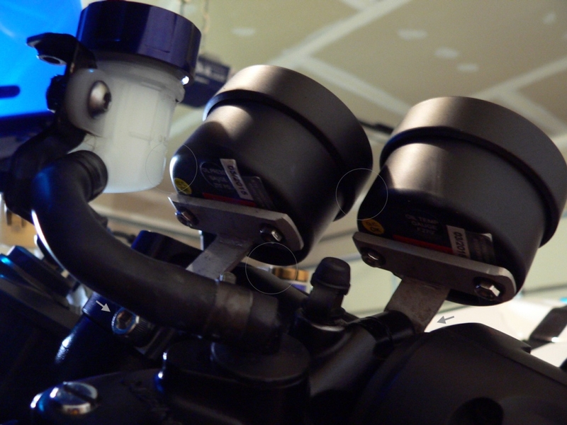
You can see my handlebars accessories bracket in BRACKET SCIENCE thread for some information on how to make your own brackets. If one gauge is positioned on each master cylinder clamp instead of both on one handlebar, that will not be too difficult and the fluid reservoirs will not need to be bothered with either.
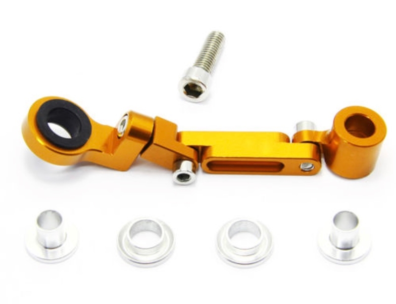
Another possibility for gauges mounting is to order multi joint brake fluid reservoir brackets and fasten them to the same points that I have used. You can adjust them to fit the exact angle you desire. These little aluminum brackets are really cool looking and they are available for cheap on Ebay. You will need to attach a mounting plate like I have on my brackets. Probably also cut and drill an inch long piece of aluminum to raise the mounting point on the front of the triple tree clamps but that will be far less work than making a whole bracket.
For a really quick and dirty gauge install, I’ve been told that Goop adhesive/sealant may applied between the metal parts and the parts be taped while the Goop cures. Goop has an inherent vibration damping effect, is extremely strong and can be removed by grabbing with a needle nose pliers and rolling off. I would test it on a piece of painted scrap metal and if it works, I’d trust it as much as bolts to fasten small objects to the bike.
15. Tighten the nuts that secure the gauges to the brackets with a 6 mm wrench. The studs on the back of Glow-Shift gauges are delicate so don’t tighten them more than it takes to compress the lock washer which should be placed between the nut and bracket. If you can’t fit the lock washer with you mounting plate, use a small amount of nonpermanent thread locking agent.
For brackets made of thicker material like 1/8’ aluminum, you may use the extenders included with the Glow-Shift gauge. The extenders would probably have worked with the brackets I made but I would have needed to use a quarter inch grommet for vibration damping instead of the eighth inch grommets and that is all starting to seem pretty bulky for a motorcycle. I didn’t use the lock washers or locking agent. The rubber dampeners will probably keep the nuts from vibrating loose but I applied a piece of vinyl over them just in case.
* Last updated by: Rook on 9/9/2017 @ 9:13 PM *