Move Close
Welcome to zx14ninjaform.com!

You are not logged in.
New Topic Reply
Next Page

Page: 1 2 3

Previous Page

Thread: camshaft runout, cap wear and lobe wear

Created on: 09/24/11 03:44 PM

Replies: 53

Rook


Rook's Gravatar

Joined: 03/28/09

Posts: 20604

camshaft runout, cap wear and lobe wear
09/24/11 3:44 PM

The SM says to Remove the camshaft (see Camshaft Removal). •Set the camshaft in a camshaft alignment jig or on V blocks. Measure runout with a dial gauge.


I can picture the setup.
Think I can get a cheap dial gauge from HF.
1. Can I simply cut 2 wooden blocks with 90 degree V cutouts and cradle the camshaft in the Vs? Then turn camshaft and measure rotating surface against dial gauge which is held stationary by some sort of bracket??

Cap wear is measured by how much a chunk of plastigage gets squashed between the cap and the Camshaft journal. I think that will be quite elementary as long as I can get a hold of some plastigauge.


Now cam wear??? I can just use a caliper or a micrometer that measures to 1.5 inches or more (service limit is around 1 and a third inch) to check measuremet from point of cam to the opposite side of cam...right?


* Last updated by: Rook on 9/24/2011 @ 3:50 PM *


'08 MIDNIGHT SAPPHIRE BLUE Now Deceased

Link | Top | Bottom

Hub


Hub's Gravatar

Joined: 02/05/09

Posts: 13723

RE: camshaft runout, cap wear and lobe wear
09/24/11 9:52 PM

1. Surface plate. You'll need slate universal. This is where you know you can set your V-Blockes from end to end being X'd. Throw the cam on the v blocks, you can send the dial from one end to the other with precision on the Y factor. Slide a bunch of steel plates on the surface plate with the feeler gauge = Down Town! Gotta have!

2. V Blocks. 
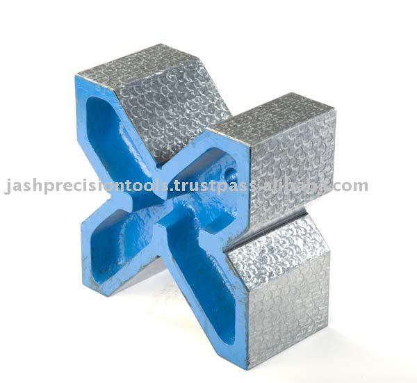
Check the deep and shallow throats in the V. This is more universal so you can drop a cam in one, a crank throw in the other.

3. Dial indicator stand. Call it a stick stand. The other type is the locking arch type. They more flex a little, where a rod type will not; apples to oranges. The stick is X to Y, The ratchet flex type is degree it to any angle.

Usually, I find a lot of guys selling out their worldly goods and at some swap meets, they sell machine tools, dial indicators, things that would cost way less if bought new. And if the dial was never dropped and the needle w/gears are smooth through the stroke, buy it.

Now cam wear??? I can just use a caliper or a micrometer that measures to 1.5 inches or more (service limit is around 1 and a third inch) to check measurement from point of cam to the opposite side of cam...right?
Do you see what you need now? To go from one end to the other for runout?; you need precision tools, not wood tools sort of. However, I understand that 2x4 try or 2 thick plexiglass, sandwiched then spin it 45° to get the v throat kind of try in the cheap seats. If you are going to do it, tool up with the right equipment.


Tormenting the motorcycling community one post at a time

Link | Top | Bottom

Rook


Rook's Gravatar

Joined: 03/28/09

Posts: 20604

RE: camshaft runout, cap wear and lobe wear
09/25/11 5:13 PM

Surface Plate
As I see it, If the V blocks supporting te camshaft ends are not on a perfectly level surface that will not make much dif as long as both remain exactly as they were set. Also, the dial gauge must not move. As long as those 3 points stay the same, the out of roundness in the shaft rotation will be very accurately detected by the dial gauge.


But you are the expert Hub and I love perfection so I will be glad to spend another $25 to get a 15" x 11" granite surface plate for off of Amazon. After all, we are measuring as little as .001/inch. The Cshaft is ~14.5" from end to end so that will work.

V Blocks
Amazon has a bunch of these too and many can be had for $50-$17. The important thing will be the dimensions because ideally these things should cradle the outer journals. Less than 7/8" between the cams so block cannot be much more than 3/4 inch thick. Might be hard to find??

The cam lobes protrude about 1/2 inch from the shaft so the blocks will neeed to hold the shafts a bit higher than 1/2 inch so that the lobes will clear the plate.

I really like those blocks you pictured above Hub but that co is from India. Good luck ordering from them.

Dial Indicator and Stand
I bought the gauge at HF last night for $9. I also got a boom type stand like you describe for $11. It has a cool on/off switch magnetic base (though I don't think that will be used on a granite plate). HF also had the steel beed dial holder w/ inner cable tensioner locking . Cool idea but like you, seemed to me that it would be less steady than the boom.

Thanks for taking the time to explain these items, Hub. I will post pics of the procedure, of course.


* Last updated by: Rook on 9/25/2011 @ 5:19 PM *


'08 MIDNIGHT SAPPHIRE BLUE Now Deceased

Link | Top | Bottom

Rook


Rook's Gravatar

Joined: 03/28/09

Posts: 20604

RE: camshaft runout, cap wear and lobe wear
09/25/11 7:45 PM

The important thing will be the dimensions because ideally these things should cradle the outer journals. Less than 7/8" between the cams so block cannot be much more than 3/4 inch thick. Might be hard to find??

have a few hours of web surfing spent looking for V blocks. Non are going to work because they are all over 1" long. The only thing I could think of doing was to hack saw/file/sand/polish a slice out to fit the journal width. Hopurs of work on hardened steel. I would have to wonder if I was defeating the purpose of all this precision by doing the chop job.

Then I found these!! It's the 18 model on the left. There was a similar set for +$300 but these are ~$50. The narrow V will work great and there will definitely be no problem with cam lobe clearance.


'08 MIDNIGHT SAPPHIRE BLUE Now Deceased

Link | Top | Bottom

Hub


Hub's Gravatar

Joined: 02/05/09

Posts: 13723

RE: camshaft runout, cap wear and lobe wear
09/25/11 8:45 PM


You lay the ends of the cam at each V block. This lets you hand spin for wear/bend. Again, you are looking for a cam that was smacked up against the towers with a valve breaking, collects some parts and when the piston comes up, it will push the clearance way down the road and there is your runout with a bent cam scenario.

Again, you are wasting your time with a too new of an engine; checking for wear. Put it together or that dust is more like; now buy the measuring tools with that grit in the oil and covers. You'll be wearing that bike out having exposed the main opening, like performing heart surgery for weeks on end with the same patient! LOL


Tormenting the motorcycling community one post at a time

Link | Top | Bottom

Rook


Rook's Gravatar

Joined: 03/28/09

Posts: 20604

RE: camshaft runout, cap wear and lobe wear
09/26/11 10:13 AM

You'll be wearing that bike out having exposed the main opening, like performing heart surgery for weeks on end with the same patient! LOL

Gotcha on that. The motor is open but covered and wrapped taped in plastic and the whole thing sits under a bike dust cover that touches the floor. The removed parts are wrapped in plastic too. If I can get these Vblocks in a few days, I don't see why not to leave it open a few more days after all this time.

That is some really cool looking stuff you got there. I love that old analogue precision equipment that was kept in wooden cases.

You lay the ends of the cam at each V block. This lets you hand spin for wear/bend.
Yep, this is clearly illustrated in the SM p 5-21. There are fulcrum points on the ends of the shaft but they are on the outermost journals. There is a cam on the butt end of the left hand side of the shaft and the flange to attach the timing sprocket on the right butt end. Can't place the flange or the cam in the Vblock or it will be doing the wobbldy woop from the get go. So, the V must be thin enough to fit on the less than 3/4" journals.


* Last updated by: Rook on 9/26/2011 @ 10:14 AM *


'08 MIDNIGHT SAPPHIRE BLUE Now Deceased

Link | Top | Bottom

Rook


Rook's Gravatar

Joined: 03/28/09

Posts: 20604

RE: camshaft runout, cap wear and lobe wear
09/26/11 10:14 AM

.........yes, it sure would be nice to actually ride the bike for a few days before winter, LOL.

BTW, the V block I was interested in with the thin walled V is only sold as a single. No matched set. I found numerous V blocks that were designed exactly like that one, some reasonably priced, some very expensive. None were sold in matched sets of 2.

So, I guess I will get a cheap matched set and hack saw out a chunk on each block. Should be ok as long as I smooth any burs off.


* Last updated by: Rook on 9/26/2011 @ 12:07 PM *


'08 MIDNIGHT SAPPHIRE BLUE Now Deceased

Link | Top | Bottom

Rook


Rook's Gravatar

Joined: 03/28/09

Posts: 20604

RE: camshaft runout, cap wear and lobe wear
10/08/11 7:20 PM

Finally got all my tools and ready to finish this up. Dial gauge, magnetic base, V blocks(which I had to cut down to fit journals on ends), surface plane.

The dial gauge showed .002" runout on the first cam shaft I tested. Standard is .0008 inches. Service limit is .004"

So, it seems there has been some warpage that has occurred. I'm half way to a new camshaft, Hub. I think it was worth the extra weeks w/out the 14 running to test this at 27-28K whatever miles I have now .

I will show pics soon. Crappy incandescent lighting tonight.


'08 MIDNIGHT SAPPHIRE BLUE Now Deceased

Link | Top | Bottom

Hub


Hub's Gravatar

Joined: 02/05/09

Posts: 13723

RE: camshaft runout, cap wear and lobe wear
10/08/11 10:07 PM

Now I wish we did this both at the same time. Here is how you look at your 3 book numbers:

.0008 ~ I am fresh out of the package. Better make sure I my runout is QC'd to that number before shipping. Pre-check because post office clown dropped or drove over it, alleged. This is brand new ready to install. Oh look! It took a wrinkle~ With all that flex on the one cam chain side, the 16 bumps in all kinds of flex to open the lagging with no weight to keep it from flexing on the opposite side.


.002 ~ Says that I am half way worn out from all the bumping. That has to light up the wallet fold; don't forget the hand rub is one hand is the cam. The other warm hand rub, is rub out that other clearance you ask yourself in the parts changing walk. Say? Which hand stayed cold if we rub parts and score both surfaces to make the score happen = Order a new head. We no longer have inserts via Z1 first year engine design. We no longer can install cam towers via a Honda design. This is a throwaway part in the cheap seats is this bike's production run. More of your, 'planned obsolescence.'

.004 ~ It took a whole bunch of wear me out miles that will begin to nickel and dime you if that engine accelerates that fast, like think about doubling your miles. It probably starts to slow down, or things become sluggish, harder starting, uses oil more than it used to. Serviceable limit says, 'technically' this is book limit. There is nothing that says it can't go 005" or .006" more and still be as quiet as a mouse... In some areas.


Tormenting the motorcycling community one post at a time

Link | Top | Bottom

ethin14


Location: Qld Australia

Joined: 03/09/09

Posts: 589

RE: camshaft runout, cap wear and lobe wear
10/08/11 11:48 PM

.0008 maybe when it was new {maybe]

.002 mid life crises

.004 run thicker oil

There is nothing that says it can't go 005" or .006" more and still be as quiet as a mouse... In some areas.

got to old to spend to much love on her now, rider her till she stops

Link | Top | Bottom

Rook


Rook's Gravatar

Joined: 03/28/09

Posts: 20604

RE: camshaft runout, cap wear and lobe wear
10/09/11 5:42 PM

I just measured again in the daylight. Inlet cam shaft, .0023" runout.

Exhaust cam shaft, 0 nothing I can really see on my needle gauge.

I tried on center on the middle journal and over to the far right edge of the middle journal. Both show NO runout that I am able to measure. I have a very inexpensive gauge but Looks like less than .0008 even. I would see that. I can see .0003 (even though it is an estimate, I can see it). It may be possible that the shaft warped into a more perfectly straight piece. lol prolly not. I'm not going to worry about it as long as it is in service limit.


* Last updated by: Rook on 10/10/2011 @ 8:27 PM *


'08 MIDNIGHT SAPPHIRE BLUE Now Deceased

Link | Top | Bottom

Rook


Rook's Gravatar

Joined: 03/28/09

Posts: 20604

RE: camshaft runout, cap wear and lobe wear
10/10/11 8:25 PM

Measured cam wear. All were in standard spec range for brand new cams. Both shafts.


* Last updated by: Rook on 10/10/2011 @ 8:27 PM *


'08 MIDNIGHT SAPPHIRE BLUE Now Deceased

Link | Top | Bottom

Hub


Hub's Gravatar

Joined: 02/05/09

Posts: 13723

RE: camshaft runout, cap wear and lobe wear
10/10/11 8:31 PM


Tormenting the motorcycling community one post at a time

Link | Top | Bottom

Rook


Rook's Gravatar

Joined: 03/28/09

Posts: 20604

RE: camshaft runout, cap wear and lobe wear
10/11/11 6:40 PM

Hi Hub. I put the camshafts back in and positioned the caps and bolts that hold them down. Everything is in place but loose.

The Book says to position the caps in the specified order according to what number is molded on the cap. Very easy, left to right, exhaust to inlet, 1, 2, 3, 4. simple.

Next step, draw up all bolts in caps and chain guide so that the camshafts are seated. Torque according to specified tightening sequence. That is where they lost me. There is no tightening sequence specified in word or diagram that I am able to find.

Any ideas????????

I found a diagram for a 2003 ZX-7 cam cap bolt tightening sequence. Cannot find anything for the ZX-14.

ANy help you can offer much appreciated.


'08 MIDNIGHT SAPPHIRE BLUE Now Deceased

Link | Top | Bottom

Hub


Hub's Gravatar

Joined: 02/05/09

Posts: 13723

RE: camshaft runout, cap wear and lobe wear
10/11/11 9:13 PM

Draw down the caps all even. Watch the split on the bottom of the cap(s). Make the cap land level and flat by using a large X pattern on the outside, move your way to center. Work from center, move out to the ends of the caps. No matter how you do it, the cam lobes that are up, will have to be pushed down, but using the 4 bolts in the cap to be X'd in pattern being pushed down on the cap(s).

The more you push each cap down, you will be coming around on the larger X pattern and begin to make that pattern go narrow. Once the caps are sent home, then do you make the tiny X pattern on each cap now. But this time, if cap A or cap 1 is all buttoned down, as are each cap, then you torque each cap to spec on the big X again. This time for example, look down at the head.

Cap A is top left corner. Cap D is the first cross of the X. D would be the lower right position. It is now time for the 3rd cap. You can chase cap B as the next crossover, or use C as the next crossover. As long as you have an X pattern going on the cap sequence, this is how simple you home the caps, then X the caps. Then home each cap in the X patter as you X all 4 caps in the same X pattern. To recap:

1. Spin all the cap bolts down in a long X pattern using the 16 plus cam cap bolts.
2. Once all the caps are bolted down, torque each cap in an X pattern.
3. As all the cap bolts have been sent home without a torque to them, you now X each cap in a patter of the X move. Then, move to the next cap in the X move of all 4 caps being bolted down. You were lowering the cam guild cap tower as well doing all the other caps in the X pattern.

When the tensioner is pushed from the back hole with a static screwdriver, you should see the cam timing should be lined up as per your, 'chain over the same tooth pattern.' This should line the cams up in perfect time again.


* Last updated by: Hub on 10/11/2011 @ 9:19 PM *


Tormenting the motorcycling community one post at a time

Link | Top | Bottom

Rook


Rook's Gravatar

Joined: 03/28/09

Posts: 20604

RE: camshaft runout, cap wear and lobe wear
10/11/11 9:44 PM

Thanks, Hub. I get what you are talking about. Big X draw up snug from cap to cap, 1,4,2,3. Small x tighten down each of the 4 bolts on the cap in a criss cross pattern diagonal front left , back right, front right, back left.

I could actually see doing this Big X over and over several times to get the shafts pressed back down in there gradually. A series of Big Xs. That is how I loosened them up. A little at a time going one bolt to the next and they all rose up pretty even. The camshafts are riding up on the lifters to the left at Cyl #1. Cyl #4, they lay snug in their saddle. The chain guide cap touches the top edge of the head all the way across.

I'm sure you know what I am speaking of. You can see it in the picture above.

Maybe I will use the 2003 ZX-7 cam cap tightening sequence for the final torque. Looks like they want the inners locked down first. Then the outers. Still, you see a diagonal pattern repeating throughout the beginning of the sequence.

You know, I never trust the first torque when there are several bolts that hold one piece. I a;ways go back to the beginning and recheck each bolt. Usually they will take a tiny bit more of a turn the second and even third time. I imagine I will be patterning all across this thing before all bolts are at the correct torque.

I am not quite ready to put this beach back together yet. There is one more camshaft test. I have some Plastigauge and i will be testing the ware of the caps with it. Then she goes back together!


* Last updated by: Rook on 10/11/2011 @ 9:51 PM *


'08 MIDNIGHT SAPPHIRE BLUE Now Deceased

Link | Top | Bottom

Hub


Hub's Gravatar

Joined: 02/05/09

Posts: 13723

RE: camshaft runout, cap wear and lobe wear
10/11/11 11:28 PM

You got it. Use the drawing. Pretty soon, you can run the mirror in reverse. If you want to tighten from the highest number down, or the lowest number up? Who gives a granny cookie, you eat it upside down with the frosting on the bottom or flip it over and X it that way. Either way, it goes down the gullet. And yes, I am anal in the X the Y, zig and zag, round and round she goes, where is that loose bolt? = I got everyone don't worry! I anal-dit.

Are we over the hump with the cam timing? That is hump one. Hump two is to make sure you torque once on the fulcrum arm. We have no clue what hand tight is... YET! That is your hump T dump T handle kind of feel. And when I mean dump, you dump too much load on a 6mm bolt thread made out of aluminum? Up comes a little coil of aluminum that WAS your threaded head hole. Now, it's just a hole in the head.

Hole in your head you begin to get a feel for the bolt to thread tightening. Here is how your bolts go down. By hand, you are with your 10mm box side, going at each bolt; one hand is on the opposite side of that wrenched bolt, you with the other hand... Feels the other bolt "UNLOAD!" That is sort of your balancing act to square the caps down. Turn and twist, meaning, turn the wrench, help twist down any loose bolt with the freehand.

This way, you can feel the cap move down in a square to the X. See your Y pattern as you have to go farther out to the farthest cap to square that which is next? Well, somehow, you have a starting point, right? So as you have to start at one end, by the time you are going so slow from one corner to the other, you eventually end up at the other plane of the cam you started at... Now, that cap on the end of the cam cap you started with, this will now be moved down in the same slow moving increment and square that cap down.

You will see the cam chain slack move taught. The caps will move the cam lobes over the bucket and this will take that swayback look of the chain all taught again. Here, you move so much slack or watch it more like. Those marks should line up again. Do you understand you did not place the chain at TDC, but who cares? As long as you marked the 3 chain to cams to crank, she now uses those as your timing marks. Lucky you. We dunt need no stink'inn pin count per manual.

We square with the book sequence loopholes you are coming up with? Novice mistakes are not really? You don't follow book sequence, who cares! The big time hump to all this is that bolt to thread torque. You need that inch pound torque with a bar in the middle of the shaft. That gauge is all a mirror opposite of torque scales. That is so you can torque left hand bolts too. But more, you want to see how much that OEM air gun was set at? And I can tell you on the push of the inch torque, it was breaking right at book. I would see 101 and to see 05 break? I think it was close to book 106 inch pounds.

To use the torque wrench, think in increment breakdown. Say we have 106 inches to load up to. We start at 25 inches on the X pattern. We go back to #1, load 50 inch pounds and so on. This way, you get to feel all those pressures up to 106. I stopped at 101 because that will never move without the extra 05 inches? No, more like thread integrity for the next round of shims. Then, when you get a feel for that thin a bolt, you can buy a set of T-handle wrenches. Make sure that 8mm is in there. That, and the 10mm for all your little hanger stuff.

Get a feel for the hardware, you'll never see a heli-coil set or know what one is you get the torque feel down.


* Last updated by: Hub on 10/11/2011 @ 11:30 PM *


Tormenting the motorcycling community one post at a time

Link | Top | Bottom

Rook


Rook's Gravatar

Joined: 03/28/09

Posts: 20604

RE: camshaft runout, cap wear and lobe wear
10/12/11 10:08 AM

You got it. Use the drawing.

Okay, we'll X it big, x it small, then the final torque 3x over in the pattern/diagram above. No way those caps will NOT go down perfectly square.

round and round she goes, where is that loose bolt? = I got everyone don't worry! I anal-dit.

+1 here. #1 bolt does all the squeezing on the first torque. The next bolt puts a tighter squeeze on the part and then the one after that squeezes a bit more. Come back to #1 bolt and it is now almost loose. You have to gov around again to get them all perfect and a 3rd x just to make sure.

Are we over the hump with the cam timing?

I hope so. If that was as simple as getting the timing chain back on the same teeth as they came off of, it's done! You can see the black mark on the exhaust sprocket/timing chain. There is also a white mark put there at the factory between the inlet sprocket and the timing chain.


you dump too much load on a 6mm bolt thread made out of aluminum? Up comes a little coil of aluminum that WAS your threaded head hole. Now, it's just a hole in the head.

zoiks, good warning. Thanks. I have to watch that because i am more person meaning I usually go for MORE rather than less when I estimate. Brings the art of estimating to a whole new level when you start to weigh in the MORE factor along with everything else.

Here is how your bolts go down. By hand, you are with your 10mm box side, going at each bolt; one hand is on the opposite side of that wrenched bolt, you with the other hand... Feels the other bolt "UNLOAD!" That is sort of your balancing act to square the caps down.

Thanks Hub. That is another great tip. Think I may have done that sort of thing before but to hear it in words gets those synapses a'snappin' ----we have a precision torque hardwire in the brain now. Thank you very much, sir. Turn one bolt feeling through the wrench the threads draw up, twist with the fingers on the opposing bolt for even greater tactile sensitivity.

That gauge is all a mirror opposite of torque scales. That is so you can torque left hand bolts too. But more, you want to see how much that OEM air gun was set at?

I also have one of those beam torque wrenches as well as a couple clickers. The beam is best for the smaller, lighter torques. As far as checking factory torque, I can tell it is sometimes way under. The head cover bolts--they were not tight at all. Barely more than Snug. That is why the head gasket was leaking, i'm sure.

To use the torque wrench, think in increment breakdown. Say we have 106 inches to load up to. We start at 25 inches on the X pattern. We go back to #1, load 50 inch pounds and so on. This way, you get to feel all those pressures up to 106.
Yeah,,,, There is another little technique that I have just done on instink from time to time. That follows with the gradual overall BIG SQUEEZE concept we are talking about. You gotta squeeze those parts all over evenly!! Helps very much to hear you verbalize it.

I stopped at 101 because that will never move without the extra 05 inches? No, more like thread integrity for the next round of shims.

You have a million of them today, Hub! I'll also torque just shy of spec to save on thread wear. We know I will be back in here quicker than most with my minimum valve clearance adjustment I am doing (.006" Inlet : .009" Exhaust) I will definitely be checking again in 5,000 miles or less.


'08 MIDNIGHT SAPPHIRE BLUE Now Deceased

Link | Top | Bottom

Rook


Rook's Gravatar

Joined: 03/28/09

Posts: 20604

RE: camshaft runout, cap wear and lobe wear
10/12/11 10:25 AM

Do you understand you did not place the chain at TDC, but who cares? As long as you marked the 3 chain to cams to crank, she now uses those as your timing marks. Lucky you.

Did not place the chain at TDC?? Now please don't make me go and SHeet my pants, Hub!

This IS TDC compression stroke of Cylinder #4, is it not? That is where I left the motor after checking the second set of clearances (the first set being the 8 valves that are up for check at TDC of #1).


This is how it looked before removing the camshafts....

This is how the timing wheel looks...then and now....

......Here it is now with camshafts going back in (just to do the plastiguage cap wear test).


Hope that IS TDC #4 or I am back to the fugging drawingboard on the clearance check and adjustment. Did I check at the wrong point? NO--couldn't be. could it?


* Last updated by: Rook on 10/12/2011 @ 10:28 AM *


'08 MIDNIGHT SAPPHIRE BLUE Now Deceased

Link | Top | Bottom

Rook


Rook's Gravatar

Joined: 03/28/09

Posts: 20604

RE: camshaft runout, cap wear and lobe wear
10/16/11 9:02 PM

well, well, WELL-


Just got a pdf of the 2010 ZX-14 SM. Camshaft cap diagram was updated. Shows proper tightening sequence.

The bolt torque sequence for Camshaft Caps is NOT the same as any discussed on this thread. It is not even what I consider a criss cross pattern.

.....see, this is why I take so long on this sh!t. Have not forked up on anything yet but sure have missed a buttload of riding.

Said it a million x, "better to be a perfectionist than a half-assist."


* Last updated by: Rook on 10/16/2011 @ 9:05 PM *


'08 MIDNIGHT SAPPHIRE BLUE Now Deceased

Link | Top | Bottom

Hub


Hub's Gravatar

Joined: 02/05/09

Posts: 13723

RE: camshaft runout, cap wear and lobe wear
10/16/11 9:52 PM

As long as you X pattern, they can anal the angle updates all they want. Harley wants it done this way in the book and I did it the same X way but if both bikes are still running with the old torque sequence, it sure is not hurting how smooth this bike runs, starts, sounds cold or hot.

I knew you were out of crank position, so we used that 3-point marking mistake to an advantage. Glad you did it. Shows you how much you can get away with once you play with enough engines.


Tormenting the motorcycling community one post at a time

Link | Top | Bottom

Hub


Hub's Gravatar

Joined: 02/05/09

Posts: 13723

RE: camshaft runout, cap wear and lobe wear
10/16/11 9:56 PM

Now, one more time. Are your valve clearances all squared away?

1. That hand tightening sequence was for no torque values, but how to feel 80 in pounds by hand and stop.
2. That means, all my bolts are down to just tight. I'm not about to torque to spec to recheck one round of shim work.
3. That mean, I can break the bolts loose by hand again, know who needs to be changed, I'm on my second check, right Rook?


Tormenting the motorcycling community one post at a time

Link | Top | Bottom

Rook


Rook's Gravatar

Joined: 03/28/09

Posts: 20604

RE: camshaft runout, cap wear and lobe wear
10/16/11 10:15 PM

1. 80' lbs, just to check clearances adjusted. Save on the alum threads. Sounds like a plan.

2. right-O This is just a check --I may be taking it apart again (OH PLEASE JESUS, NO, not again!)

3. well let's hope second check is last check.


........and I am doing the Plastiguage test to check cap wear first. Yup, the caps will come off again to measure the squashed Plastigauge.

I knew you were out of crank position, so we used that 3-point marking mistake to an advantage. Glad you did it.

I'm glad I did it, too. Just scared I checked clearances at the wrong crank position. That SHOULDbe #4 TDC to check all valves on cyl #4, both exhaust on #3, both inlet on #2, nuthin on #1. What you see in the pic above is where i checked those valve clearances and if that is not #4 TDC I am sh!t out of luck. Please tell me that IS TDC #4, Hub. Yes timing wheel is lined up with marks as/ pic above.


* Last updated by: Rook on 10/16/2011 @ 10:38 PM *


'08 MIDNIGHT SAPPHIRE BLUE Now Deceased

Link | Top | Bottom

Hub


Hub's Gravatar

Joined: 02/05/09

Posts: 13723

RE: camshaft runout, cap wear and lobe wear
10/16/11 10:43 PM

You are on your own, pal. This is walk the gang plank... Sink or swim! Here is the blindfold:

1. I don't know where to start looking? Yes you do. I can find any compression stroke in any engine. How?
2. I can do it blindfolded! I can feel for the throttle body and know I am on the intake side.
3. I can reach up or now look at the intake go down.
4. I know the piston is up as the valve is going down. There is a suck action happening on that stroke.
5. I know that intake is going to come up and so is the piston to compress that which it just sucked into from pulling the fuel and air from the throttle body.
6. I don't need to watch anymore of the intake moving up. I already know it is coming up on compression.
7. I don't care if it lands on 2-3 or 1-4 if I watch any intake valve come up. I know that timing mark is for that valve.
8. I felt #2 go down and come up. So I am going to mirror the 1-4 as if it was on the 1-4. I don't need no stinking 20 pin count.
9. I don't need no timing mark either. I can chopstick a piece of safe wood into the chamber via the spark plug hole. I can now watch the stick move all the way up and stop.
10. I know my cam lobes are facing outside just like the 1-4. Think I care if I 1-4 and 2-3? Who says I can't mirror and begin at the 2-3 and feel the 1-4. I play fair. 1-4 can be the first to be inspected I start watching one valve go down and how about that. What are the odds I picked the 1-4 and that is where the book says to start.
11. Know how the engine is a mirror between 4 cylinders, you can reverse the engineering and it still matches the book.


Tormenting the motorcycling community one post at a time

Link | Top | Bottom

Rook


Rook's Gravatar

Joined: 03/28/09

Posts: 20604

RE: camshaft runout, cap wear and lobe wear
10/17/11 3:47 PM

So basically I might be almost done unless i fucj=ked up. Then I start all the fucjck the way over.

Made a discovery that cast a huge question mark over the whole project. My 06 SM shows diagram where cams point away from one another on the left. The 2010 SM shows the cams point in at one another for the same diagram. IDK if I was checking the valves for #1 TDC with #4 at TDC or if I got it right? This really burns my ass. I'm not going to ride the 14 this year. I will be fuhghing around with shims and cams until mid December at this rate.

thanks for the tips. #9 sounds fool proof. You're going to hear me fucjgkhging screaming all the way in CAli if I got this wrong.

I guess I will be finishing the cap wear test and then starting over checking everything and feeling with a dowel rod to determine TDC. Should have done that from the start.....but why would I do that if it is right in the book? Because the fuchfking idiots that translated the damn book don't know their ass from their elbow . . How the hell you get this backward? Pretty damned basic, I would say. And this is not even a case of translating words. It's a bloody drawing and they did it wrong. Either that or I'm the idiot.


'08 MIDNIGHT SAPPHIRE BLUE Now Deceased

Link | Top | Bottom


Welcome to zx14ninjaform.com!
 
New Topic Reply
Next Page

Page: 1 2 3

Previous Page

New Post

Please login to post a response.