


This was done on my 2009 Monster Edition, I assume it is the same for most years of this bike.
The US versions were not built to use O2 sensors, but there is a flat spot atop the 4 into 1 section of the headers where one would be present on the overseas models. It is pictured here (the small circle wiped clean) and is positioned to both clear the catalytic converter material yet be behind the individual header pipes for a more even reading of all cylinders. This is on the left side of the bike btw.
The headers need to be removed to do this. To get to the header flanges I only needed to remove the lower fairings. I also removed the finned cover, but don't believe this is necessary because I was able to get to everything easily through the opening in the side fairing. You can remove the side fairings if you want but it's not necessary. The header nuts are 12mm. I used a short wrench for the accessible ones and a 1/2 ratchet with extensions for the harder ones. Be careful not to nick the face of your radiator. This is a stock photo but I have highlighted what needs removed and through which fairing opening you will be working. Each lower fairing is held on by 3 smaller allen bolts along the top edge and 2 larger ones below, with a clip holding the two sides together under and to the front of the bike. The fairings need to be pulled outward like wings for removal and this will require you lifting your kickstand for the left side one.
Here is the previously mentioned flat spot drilled out. I didn't have a bit quite large enough to accommodate the bung so I used a grinding stone as well. Take note of inside the hole and be careful; this location is VERY close to the cat material as well as where the header pipes combine.
Here is my FIRST attempt. The bung I used was tapered and I welded it in as such. VERIFY YOUR CLEARANCES AND TEST FIT!!!! Despite eyeballing it and measuring, this attempt set the O2 sensor to high, not allowing installation because it hit the bottom of the motor.
Here is try #2; luckily I had another bung. After grinding the first one off I situated this one almost entirely in the pipe and welded it nearly flush. I also angled it slightly downward for further clearance, then tack welded and mounted the headers to make sure everything was right.
Here it is all welded in and CLEARING! There is JUST enough room to install and remove the sensor without having to drop the headers which is what I wanted in case it needed serviced in the future. I did not measure, but believe this with the lean of the bike will satisfy the 10% angle of the sensor Dynojet recommends to prevent rusting inside the pipe.
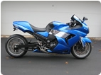
Here it is with plastics back on.
The only foreseeable issue I have is that the terminals that connect the sensor to the wiring are very close to the pipe. Mine is wrapped (see picture) so I hope the heat doesn't cause any issues here. I may reroute it after checking things out after my first ride with it.
I didn't take further pictures, but I simply routed the wiring behind the motor, up past the swing arm (zip tying it on the bracket holding the brake return spring), under the gas tank and back under the seat. No plastics had to be removed to do this, though I did have to unbolt the rear of the tank and tank bracket and lift in about 2 inches to get the wiring through.
I hope this write-up helps someone. I've not used the Autotune yet as I am waiting on a cable and termination plug from Dynojet, but please PM me if you have questions about the install itself.