


Gilles Tooling kts Chain Adjuster Installation and Safety Mod.
The Gilles Tooling kts Chain adjuster has a bad reputation for breaking while in use. The rear axle slides forward in the axle slot causing a serious safety problem. The product has been revised but not for the ZX-14 or Hayabusa. The old adjuster is no longer in production for these bikes but you may still find them available from some vendors. I got mine from OPP Racing.
Internet videos and motorcycle forum discussions document the kts chain adjusters tendency to break at the slider arm but in some instances, the information shows that the guidance framework was also broken. A look at the inside of the slider arm is enough to raise suspicion. The slider arm is a hollow aluminum sleeve that the adjuster screw threads through. 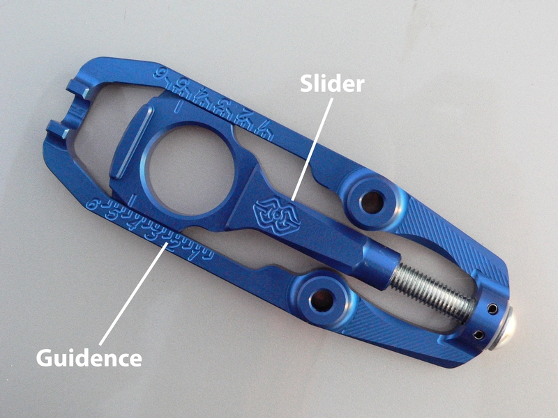
The kts chain adjuster, outer view.
I believe this product would have been a lot stronger if the slider arm were simply made solid with a hole drilled and threaded all the way through rather than than the large, open slot turnbuckle design that was chosen. 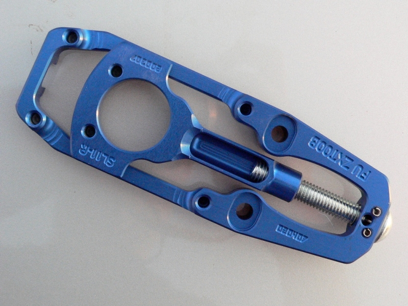
Viewed from the inside, the kts’ weak spot is revealed. The slider has a large hollow inside it’s arm. It seems possible that the permanent mount holes (small holes for optional permanent fastening to the swing arm) decrease the guidance strength.
The OEM chain adjustment equipment supports the axle by an adjuster screw [A] which pushes the axle block [B] backward. 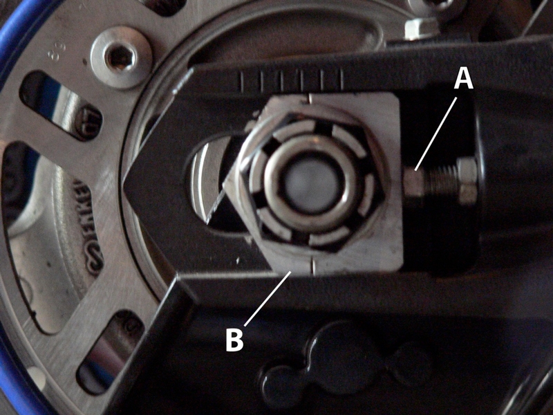
The Gilles Tooling kts chain adjuster supports the axle by an adjuster screw that pulls (rather than pushes) the slider backward. The torque of modern sport bikes apparently can cause forward force on the axle that is sometimes too great for the kts adjuster to withstand.
The standard configuration of a kts chain adjuster (as shown in the photo of below) is to have one forward button head bolt replacing the OEM adjuster bolt. This button head bolt is not used as an adjuster bolt. It only holds the adjuster frame to the swing arm. There are also two button head bolts at the back of the swing arm that hold the the adjuster from moving laterally.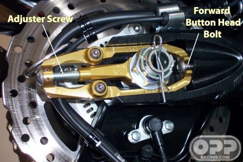
But lateral movement does not seem to be the the problem. When these things give, the forward force actually pulls the slider in half. 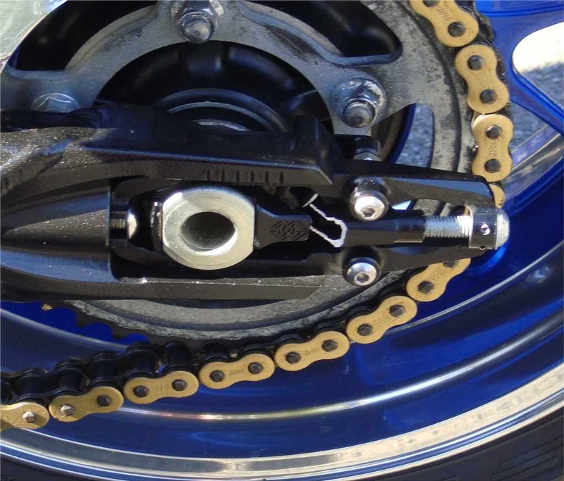
The counter part that hooks behind the swing arm does not even contact the back of the swingarm. As you can see, I was able to slide this folded piece of paper right through a gap between the counter part and the back of the swing arm. The counter part is not holding the axle from being pulled forward. It only holds the guidance firmly into the swing arm. 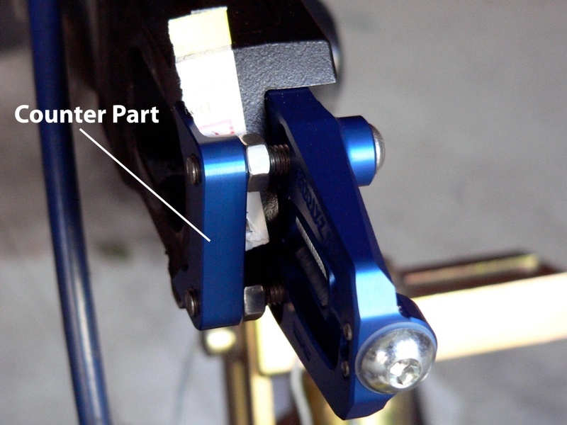
My idea to strengthen the kts chain adjuster is to retain the OEM adjuster screw so that the slider is supported at the front as well as well as from behind.
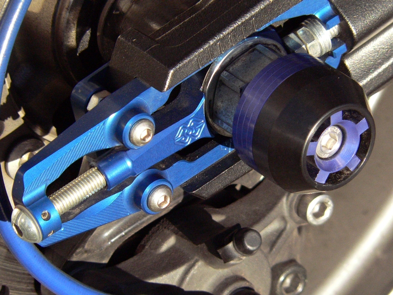
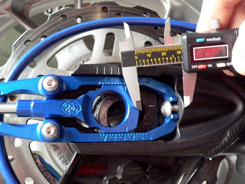
Below is my modded kts adjuster with the OEM adjuster screw and lock nut in place. There are also 3 washers placed under the locknut as shims. The shims space the lock nut away from the tapering inside of the chain adjuster so that the adjuster bolt and lock nut can be more easily reached with a wrench. 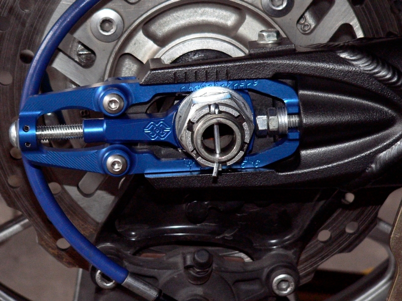
It is important to have a long enough chain to allow the axle to be centered on just a bit past the second swing arm mark (see photo above). If the chain is not long enough to allow the washers and OEM adjuster bolt and lock nut to fit, the lock nut, the bolt head or both may be ground down to a slimmer profile. It may also be possible to omit the washers, however it would require a very thin, perhaps modified wrench to fit into the forward taper of the kts adjuster guidance.
Below is a link to a Gilles Tooling kts Chain Adjusters thread I started before purchasing my adjusters. The topic deals with the safety of the adjusters and what might be allowing them to break.
Gille's Tooling Chain Adjusters
Tools:
six 7 mm flat washers
rat tail file
12mm open end wrench
4mm hex tool
non permanent thread locking agent
10mm open end wrench
1. Take note of exactly where the rear axle is in relationship to the marks on the swing arm Remove the rear axle and OEM chain adjuster axle blocks (see Wheel Removal, steps 21 through 23 and 25 and 26). It is not necessary to remove the wheel from the swing arm.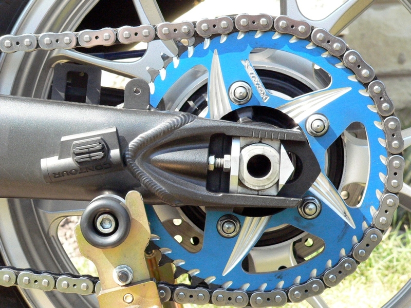
My axle seems to be centered on about 2 and a third marks.
2. Determine which adjuster you want to have on each side of your bike according to
your axle nut position preference. I tighten my axle nut on the right so the threaded end of the axle is also on the right. 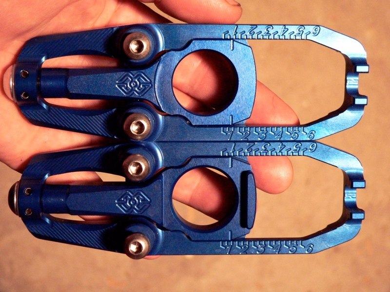
[b]Each side of the kts adjuster has a different slider. The side with the round recess surrounding the axle hole goes on the side of the bike that you have your axle nut. The side with the flat sided recess around the axle hole goes on the other side of the bike where the axle has the two flats on the end.
3. You will need six 7 mm flat washers. 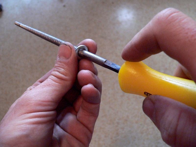
8 mm washers may work without modification. The 7 mm that I got needed to have the holes enlarged with a rat tail file so that they would slide freely over the threaded portion of the chain adjuster screws.
4. Place the adjuster into the proper side of the swing arm. Draw the chain adjuster screw locknut up to the screw head and slide three 7mm flat washers over the threads of the OEM chain adjuster screw.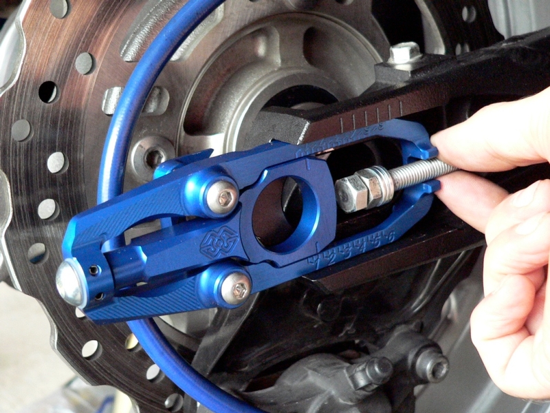
I had considered using a shorter screw in place of the OEM but after measuring, it seemed that the OEM screw was not execessively long AT ALL.
A chain of average length is used up by the time it reaches a bit past the third mark on the swing arm. I considered the fourth mark to be the maximum wheelbase I would ever be likely to adjust the chain to. I measured the distance the screw would be threaded out if it were supporting the slider with the axle centered on the fourth mark.
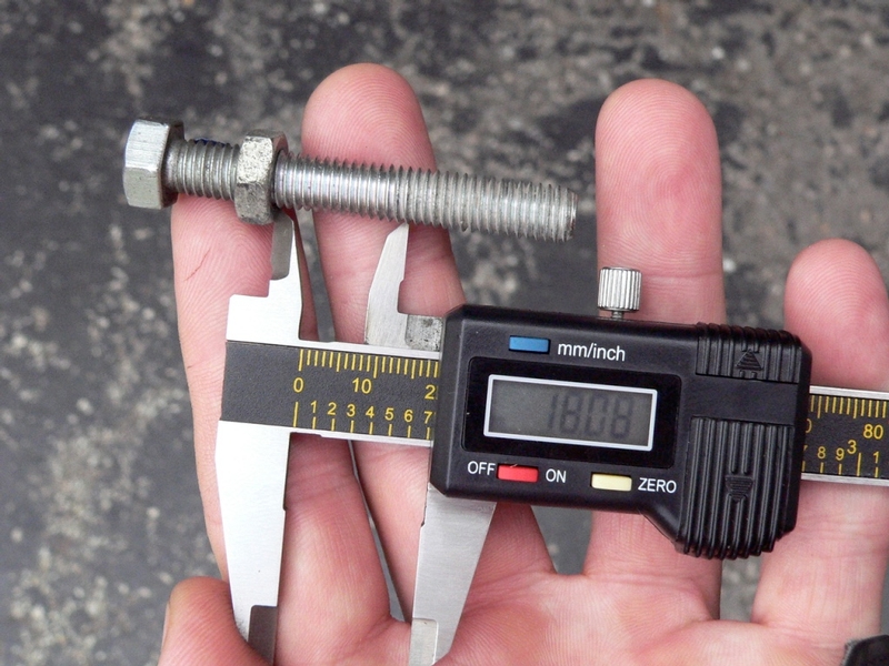
I also measured the portion of the screw threads below the chain adjuster locknut that was clean of lock tight. I assume that to be the depth of threads in the swing arm for adjuster screw. The total length of screw that I would probably ever need was about 50mm. The OEM screw is about 60 mm.
5. Snug the adjuster screw locknut with a 12mm open end wrench so that the kts
adjuster is held flush to the front the adjuster slot.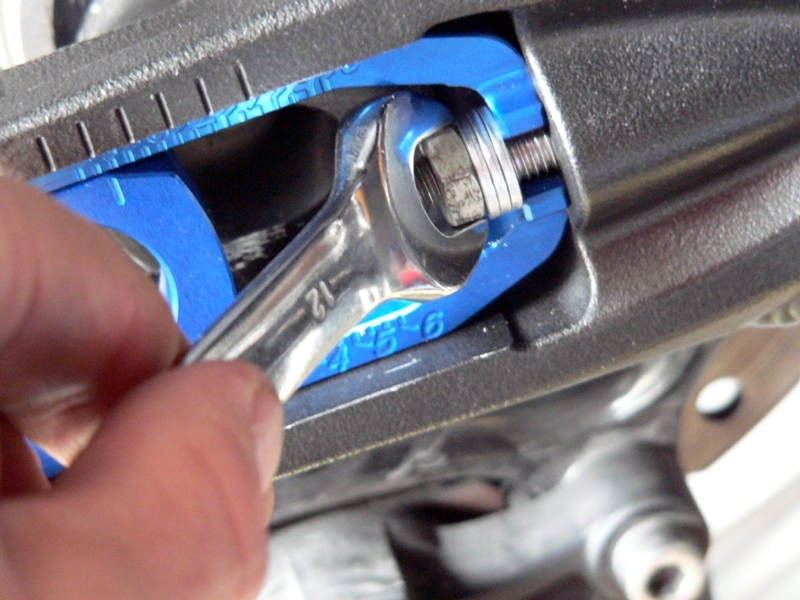
6. Use a 4mm hex tool to tighten the two screws that fasten the counter part. I also used non permanent thread locking agent on the threads.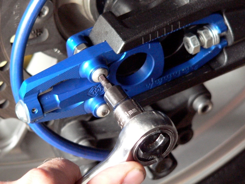
According to Gilles Tooling instructions, these screws should be torqued to 5 Nm (3.7 foot pounds). Considering how thin the aluminum hooks on the counter part are, I felt that was much too tight. I tightened them up so that they cannot move laterally and used locktight on the threads. These screws also have locknuts.
7. Tighten the locknuts using a 10mm open end wrench.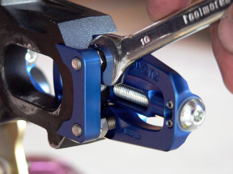
8. Pre-adjust the axle position so that it will center the axle according to the swing arm marks that you observed in step 1. Turn the OEM adjuster screw head so that it butts against the front of the slider. Tighten the OEM adjuster screw locknut against the washers. Do this the same on both left and right chain adjusters. 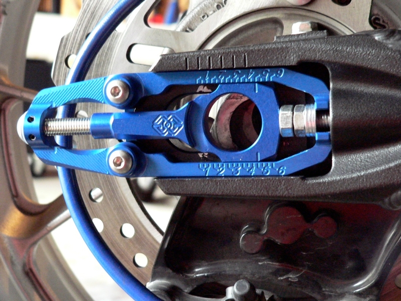
The average chain, when new will be close to properly spaced with the OEM adjuster nut and locknut both drawn up tight to the 3 washers. If this is too tight, one washer should eliminated or ground thinner. The adjuster screw head could also be ground thinner.
9. Lube the axle with High temp grease and install it through the kts adjusters with the wheel and drive chain in place. Install the OEM axle, washer and locknut. Insert the cotter pin (See Wheel Removal, steps 39 through 43))
Weights
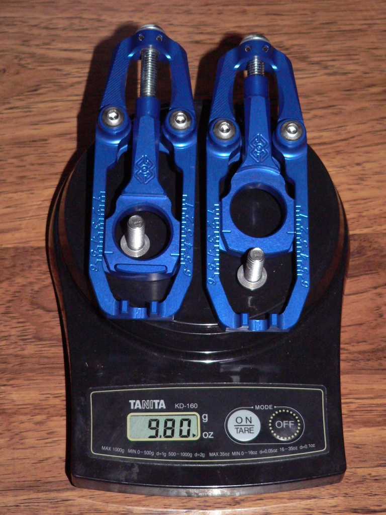
Cool mod but results in a weight gain of 6.9 oz (not including how ever many washers are used to shim the forward adjuster bolt).
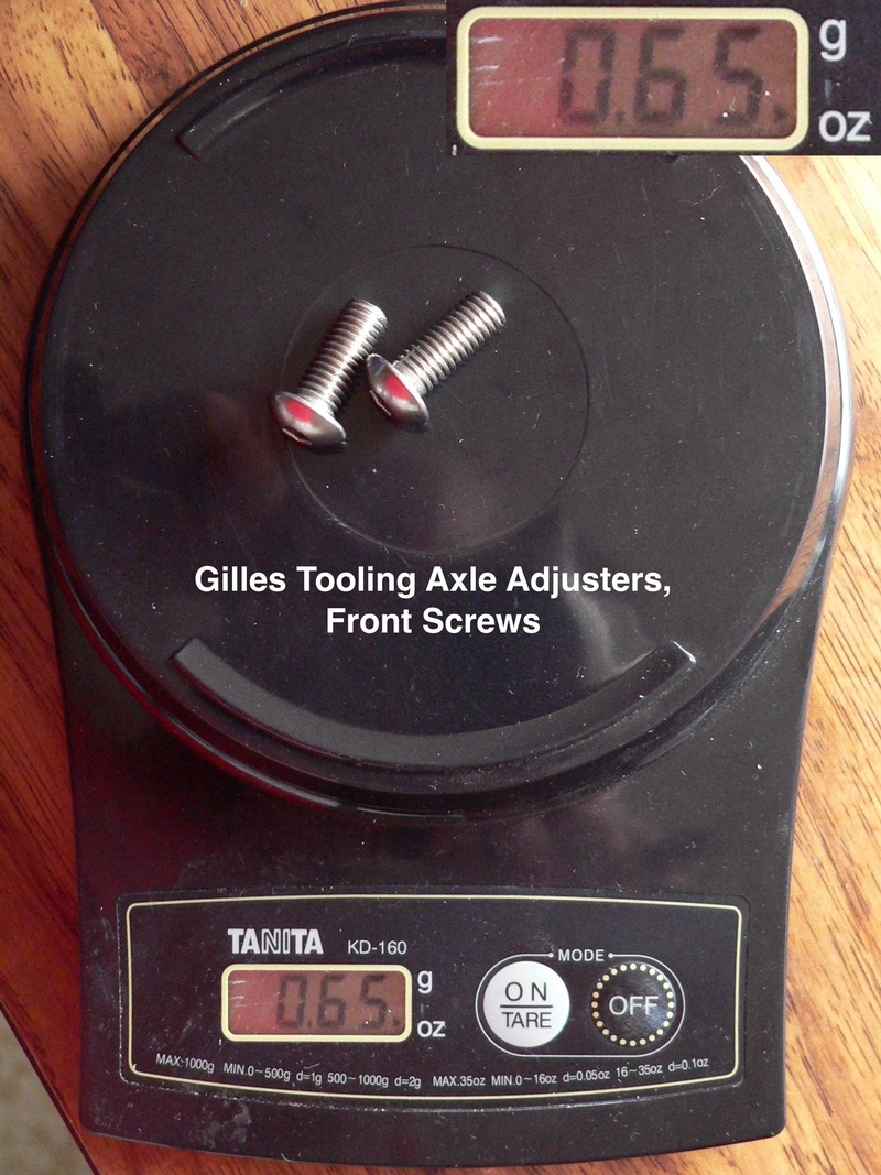
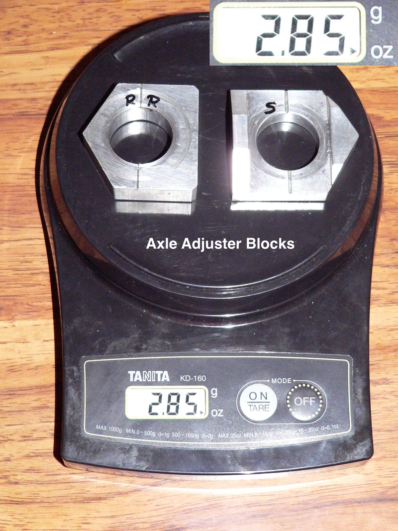
The chain adjusters weigh 9.80 oz, minus the two button head screws, 0.65 oz and the adjuster blocks 2.9 oz for a net weight gain of 6.25 oz.
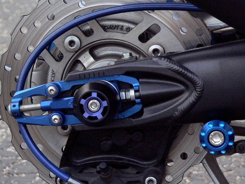
Pics of installed chain adjusters.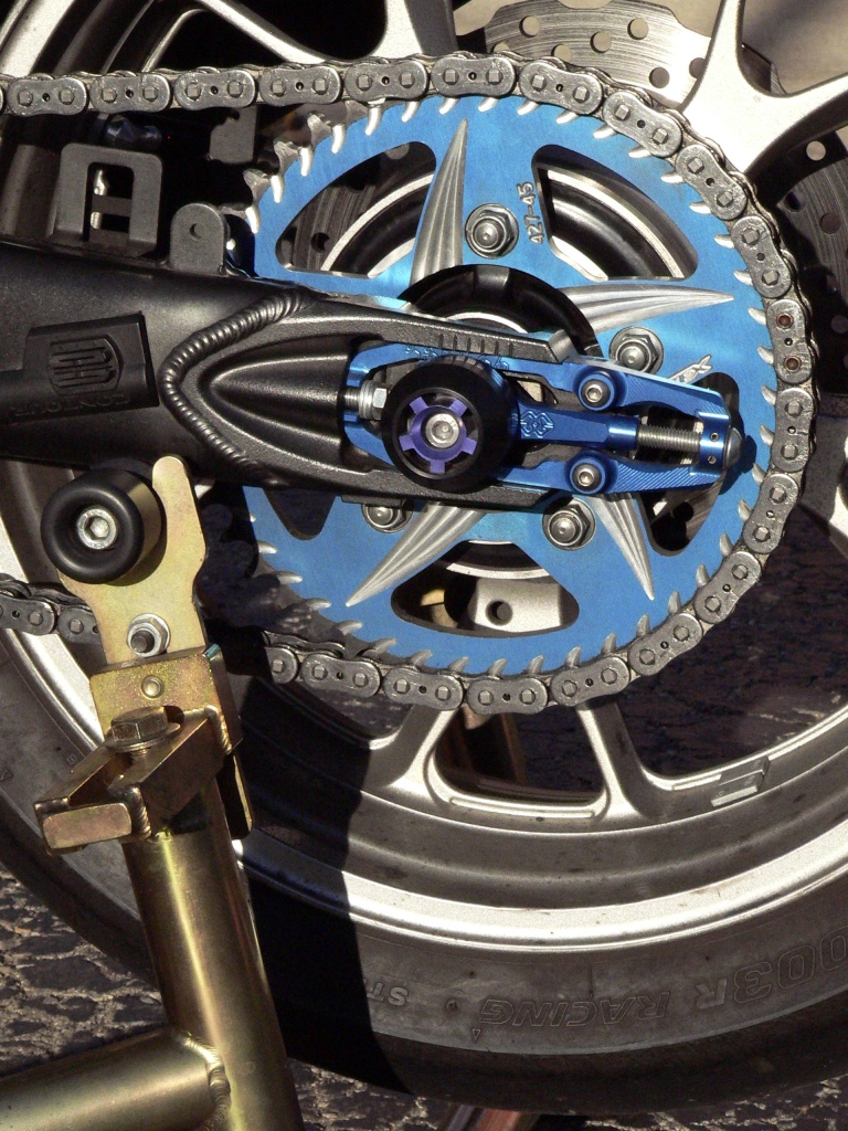
* Last updated by: Rook on 2/22/2018 @ 5:32 PM *
 Rook you have missed your calling.
 Maybe go catch it again soon.