Move Close
Welcome to zx14ninjaform.com!

You are not logged in.
New Topic Reply
Next Page

Page: 1 2 3 4

Previous Page

Thread: Ping Hub ZX-14 Tachometer Problem

Created on: 10/19/21 01:17 PM

Replies: 91

Hub


Hub's Gravatar

Joined: 02/05/09

Posts: 13719

RE: Ping Hub ZX-14 Tachometer Problem
10/22/21 7:41 AM

I think my next step is to pull the meter and perform the bench checks per the manual.

Okay, my mistake, I thought you already pinned the meter and found it A-OK. You didn't come back with any yes on the bench test on the bike. So you're decoding the abstract first.

So, right now the screen is off to disconnect the harness. I know we are going after the tach, but hard to say how you could loop the ECU with the water temp blink. You have no other issue but the tach bump/jump call it. What are the odds water and tach are in the loop? Cam and crank yes. Hold off for now. Let me go thru your other posts one at a time. I just don't want you to go thru the bench check for nothing.

This statement in 16-64 had me thinking:

Me too. But it's saying a flashing 'no matter who,' it's a communication error and it's as simple as that. Now, put this together and see what the book is saying:
1. Wire out of connector, but all others connected but the water temp wire = Error or sets a code.
2. Connector not connected, see it yet? And now it's zero input and no wire connected = Error or a code set.
3. Short internally, where a good known signal like 124? WAS PINGING the correct range but not anymore = Error means Code. Code means Digit.

so obviously the harness and CAN Hi/Lo lines are not connected to meter unit so gives the flashing of the water temperature gauge.

I want to walk your abstract on this one, and see if what I mentioned above is going to follow book. You are correct to the obvious so far about the harness. Now we get complicated yes or no? What does CAN have to do with benching the meter? Meter has no clue who is short/open, right? CAN does.

Might want to give this another try or maybe this helps? You now say that the harness is off and that means no power to the meter. '... so gives the flashing of the water temperature gauge.' Without power to the meter when key on, no. How could it flash the water bar. I'm sure you meant it another way.

Now mines doing this with the meter unit connected to the harness and I'm getting the water temperature gauge flash.

I'm going to address this as the generic steps, pg. 3-61.
1. Can't be the ECU. Sets and holds the backup. Bike runs with code set.
2. Can't be the meter. Shows the bars, shows it blinks.
3. Can't be joint 2 if other grounds are also jointed together in joint 2.
4. Can't be a wire drop if joint 2 connects to ECU and meter blinks.

Now for the Can Be's:
5. Can be the water temp sensor being the only thing left.
6. Can be joint 2 and back to 14 years of E in that joint causing a bad ground.

But then again, joint 2 holds more than one ground. Those should fail as well. Trying to follow wires from the water temp sensor, but are we down for a temp sensor replacement? And that means one of two things:
a. You buy the temp sensor once you follow all the leads the books sort of points out-wire wise. Could be a bad ground, or if you might be lucky and have the connector pins corroded at the [water] connector. The down side is the process you have to go thru to test the temp sensor you have now. That means you'll lose coolant for a possible replacement anyway. Testing the temp sensor is somewhat involved.
b. But if you had a new temp sensor, plugged it in and the code went away as it sits grounded on the bike. That temp does not know if it's in the water or not. Room temp is it laying on the bike to be grounded to complete the loop. But if the code remains, it's back to checking wires.

In my mind this = CAN Communication failure with the harness connected.

Here's the can/can't be... Can be a lost ground/open wire/short in water sensor. Can't be the CAN, because all it does is separate who is sending in analog and who dropped out of the loop and the CAN sees that the water temp bar is sending in only one of the same digit as data. Can't be CAN if it can set the [water] code and no one else. Can't be out of the 122~126? range if it can set a code, run the xmas lights fandango.

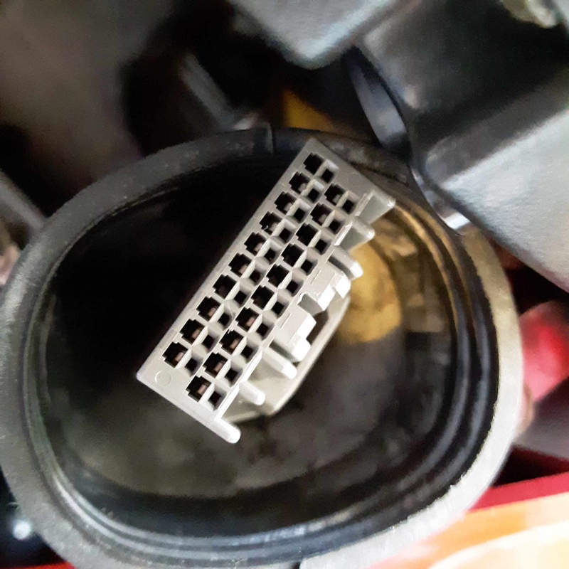
Right now, with shield off, harness out of the way of the pin count, ohmmeter set as 1x ohms, probes into pins 17 and 18, CAN will show it's within spec and you now eliminate the CAN not being a variable. Out of spec, the CAN Can't set a code, Can't keep the lights off the dash from blinking every time the key is turned on.

Also my tachometer does the sweep but no workee after starting the engine. Again a CAN communication failure?

To answer that question, and not chase tail, WATT is the ohm resistance of CAN's pin 17-18? What is the compression number that means the same thing of a working cylinder is the same as the meter working properly with that one 124? reading.

Sounds like tach unit is good due to completing the needle sweep per the bench test.

Correct. The walk:
1. Needle not stuck if sweeps.
2. ECU recognizes power on, and meter is hot as well, not a ground to hot loop problem. That walks as, wire in/wire out is saying the hot wire side goes to the jobber [bulb/sensor/black box] that needs power, so wire out goes to ground; we have a complete loop we do not have to chase, meaning. I ohm the hot wire from its source up to the jobber's plug end of that connector. That's one wire looking for an 'open' or a break in the wire. The jobber has a resistance check, so pin 17 and 18 checks resistance. Last test of 3 is to ohm the ground wire from the jobber harness end to ground. Can't be the wire loop with jobber doing its job.
3. CAN is not out of spec if it can set a water temp code and no others.

[q]Everything else on the meter unit works with the exception I'm not seeing the meter unit's red warning light come on during the key on sweep.[q]
Taking a guess, but maybe it's the ABS light and was not on the western models but euro had ABS first year. The shift light or rpm hold light while waiting at the tree at the track? I never messed with that. Chrly might chime in if you point to that red light on the meter.

Now mines doing this with the meter unit connected to the harness and I'm getting the water temperature gauge flash.

I'm taking a guess on the tree light. Go back to chapter 16, find the meter face and tell me what light on what side, near where and I'll see what light you are talking about. As far as we know, you have a water temp code. How it showed up now, I can't explain. Coincidence?

In my mind this = CAN Communication failure with the harness connected.

Let's repeat the walk:
1. Wire in-Jobber-wire out = No other code is set but the water temp sensor = CAN recognizes it and sets the code.
2. The CAN resistance is within spec = Jobber 124 ohm resistor in the meter is working = Code is found and set.
3. CAN can popup any code if shown the variables of short/open/connected or not.
4. Only pins 17 and 18 know for sure if the meter is junk. But to me and how you are explaining it, does not sound like a meter problem, but in proper function, yes?

... no workee after starting the engine. Again a CAN communication failure?

No. ECU might be the trigger source to the tach. CAN only separates all those sensor wires from the ECU to know who to set when the analog drops out.

Everything else on the meter unit works with the exception I'm not seeing the meter unit's red warning light come on during the key on sweep.

That's why I'm saying to hold off on the meter removal. Look at what you're saying. 'Everything works...' It says CAN's ohm resistance is within spec. Meter lights cycle. No problem found at the meter... think liquid display cycles/tach speedo cycle/lights come on fandango when key is cycled. Look elsewhere like the water temp sensor and either remove it and boil the water as per book, or buy a new one... no wait:
1. Original part, yes? Lettuce try a salad dressing to remove scale off the original temp sensor.
2. Solution ratio is a cup of vinny to a shot of peroxide. Drop it in a cut down plastic water bottle and let it sit to show a cleaner surface and maybe the scale on the sensor is the analog not moving to set a code.
3. Recognize the obvious rather than throw parts at it, meter wise. Scale is a thought. Internal resistance of the temp sensor is a thought. Wire drop is a thought. Bad ground at joint 2 is a thought. The Grn effect is a thought, meaning, is the water connected to the tach is not really a walk, but rather a throw at the wall and see if it sticks?

There is no explanation in either the owners manual or the service manual as to what this red warning light is for and if it should light during the initial key on sweep. Is it a master caution warning light or for EFI fail only? I don't know.

Once you point out the position of the red light, one of us will chime in and say it's a drag race assist or not, and/or an ABS light on a non-ABS bike. Cheaper to manufacture one meter as a fits all.


Tormenting the motorcycling community one post at a time

Link | Top | Bottom

Hub


Hub's Gravatar

Joined: 02/05/09

Posts: 13719

RE: Ping Hub ZX-14 Tachometer Problem
10/22/21 8:55 AM

I'm curious as to why the Service Manual doesn't seem to have a check for the harness end at the meter for CAN communication Hi/Lo lines, did I miss it?

The SM is not a variable helper. It's not a training manual. It's what I call, you better know the basics before you open that book. There's carb/points basics at the very beginning of the handcuffing is a set of points. Think about it. It's basic on/off connections. On, it flows current to the coil and saturates that copper coiling inside and takes time. Off, the coil wants to find ground with all those electrons roiling. Evolve to a computer bike and you have yet to leave the on/off basics. Only it expands as hi/lo node effect, power on/power off magnetic effect, a 1 or 0 math effect. All mean the same thing it's so fucking complex.

Once you unravel the tape off the computer harness, there is a wraparound of that wire you see in the rendering, pg. 1-6 and nothing else, basically. So you being the mechanic, your diagnosis is to ohm for breaks/open/etc. No resistors in the harness, just wires from end to end. ECU sets the code. I'll assume the hi/lo wires detect analog from digital so as to set the code. I have no clue. How else can it work? If I reverse engineer it, I need to make it work somehow to walk the logic of the intellectual property I can't see walk. Some of the walk, yeah.

The only check I saw was the aforementioned resistance check for 122 ~ 126 ohm at the meter unit CAN terminals. If I have a CAN comm fail it could only be one of three causes, a fault inside the meter unit, the CAN wires or connectors are faulty between the ECU and the meter or the ECU is not generating a CAN signal. Anything else?

I could be wrong, but when I hear measured resistance, it sounds like a jobber to me. Book never never had a chapter on wire harnesses that says to measure a computer wire from end to end to read a resistance value.

1. 122 ~ 126? check. That's correct on your part. It says to me; out from the ECU are hi/lo wires up to the meter.
a. I have to determine if the jobber-ECU>> is the fault.
b. I have to determine if the jobber-Wire harness>> has a break between wires, a connector not connected, or wire out of a connector.
c. I have to ohm a walk in the book to decipher if a jobber [meter in this case] is within spec [124?].

2. I have a self diagnosing system as to point to a certain direction thru a code set.
a. Are my jobbers in the loop within spec? Who in the loop is at fault; Meter/ECU/Wire?
b. Manual shows a jobber's spec reading. On the code page 3-43, I read what the backup says it will do. Only abstract to read is the usual; short/open/not connected of the either/or's.
c. The hindsight. Oh, if you only knew what you are going thru and boom, how easy was that in the hindsight of the complex we are going thru.

3. I am paid the big bucks to eliminate each variable and never see the hindsight right in front of me.
a. So I have to throw the time in a wire to wire break/not connected.
b. I have to have the equipment and the empirical knowledge just to open that book and begin the walk.
c. Yes, it's a process of elimination of the jobbers in the loop. It's not throw parts at it. Book shows not to throw parts at it because you do this first.
d. Oh how it ohms within spec but does not work anyway is the hindsight of how many things go wrong and you missed it anyway. Hindsight is on the way, don't worry.

So in hindsight, I'm saying, Kruz, look at how the meter reacts. Sure looks like it works, sans the needle action.
Be nice to have another ECU to plug in.
Be nice to have a new water temp sensor to plug in.
Be nice to look at compression the same way and take the ohm meter right now and pin 17 and 18 to see if it's within spec.
Be nice to bench the needles and see a clean sweep on the return, or the tach needle hangs up and does not match the speedo?

The fastest, easiest jobber to get out of the way is ohm for 124 and now keep the meter on the bike... it's not the meter.
Say yes: when I turn the key off, both needles match, tach is as home as the speedo = Can't be the meter @ ohm-my, a jobber out of the way. Windscreen back on.


Tormenting the motorcycling community one post at a time

Link | Top | Bottom

Hub


Hub's Gravatar

Joined: 02/05/09

Posts: 13719

RE: Ping Hub ZX-14 Tachometer Problem
10/22/21 10:02 AM

One last thing Hubster, is this thing safe to ride with tach and water temp gauge inop? I'm thinking, is my cooling fan getting the signal to switch on at 205 F or whatever the temp preset is? My guess is the ECU is commanding the fan to come on through a fan relay but this may be independent of the CAN comm lines.

Good question, Kruz. No, it is not independent but within the loop of the ECU. Takes the CAN to set the code. About your 3rd read of this thread, the back and forth letting the abstract of the book sink in, you're going to go... oh shit, I'm starting to get some of this.

You got the walk to pick up the puzzle piece, now walk it in place:
1. Jobber [the sensor in this case] is an analog sender.
2. The ECU is monitoring a balanced number in every jobber loop is the electrical back and forth ping. Don't think about the side stand, and an on-off switch showing the light on the dash.
3. The key goes on, that 124? is a loop connector, and shows the connected hi/lo wires that go into pin 17 and out 18.
4. I'm not looking for the problem; you are. You have the book, you're starting to catch the steps. Boring theory is bottom line basics to solve the complex is me walking your steps.
5. The ECU is commanding the fan to come on, correct. The ECU commands the CAN to set the code. That's wire out from the ECU.
6. Wire into the ECU is the jobber. ECU looks for analog input. ECU now sees zero input. Back to the kickstand if the analogy works. The kickstand was flipping up and down many times is on and off of the analog input. Now the kickstand is either up or down. This represents a digit only. It was sending analog of the kicking action thousands of times a second, but now it's just one input as 0. The ECU code is set at light speed to the 80C backup and oh btw, here is your code in a few more seconds at the meter... aka, 'Huston we have a problem.'

All the backup abstract says is: ECU sets to 176F (80C). One of the test mules had the WTS connector off and I rode it around. Just can't recall if she started to overheat, ran bucky-bronco, or the fan came on with key on and we are talking cold start. So as long as code14 is set, fan on all the time from key on till key off... if I recall. Or, read the backup and if 14 is set, we set the fan on as well.

Updated manual adds to the abstract that the fan comes on. So same code set, nothing has changed. So yes it should show you it's getting hot thru the fairing, might be in limp for sure, and if that means ignition retard, that's more overheating when the timing is not firing off gas so it moves faster, but more moves slower and heats the metal more in a boil state of what didn't fire off but cooks the air.
Rides like:
a. Fan on all the time.
b. They do not say ign is set here... so it's feel the excess heat if it feels more hot than normal.
c. Bucky-Bronco is misfire or the backup spitting the injector where? The backup's ignition where?
d. Single fan should work, but book says we code if a parameter is down NOT sending analog. See a dealer and stop riding the limp.

We are caught up to this point. Ball in your court or bench.


Tormenting the motorcycling community one post at a time

Link | Top | Bottom

Kruz


Kruz's Gravatar

Location: Anna Texas

Joined: 03/16/09

Posts: 6564

RE: Ping Hub ZX-14 Tachometer Problem
10/23/21 8:51 AM

Thanks for all the input Hubster, ball is in my court now for sure. I'll walk the book steps and see what comes up, this problem is not going to fix itself.....


2021 Aprilia RSV4 2020 BMW S1000RR 2016 ZX-10R KRT 2016 959 Panigale Red 2015 CBR1000RR SP Repsol 2011 ZX-10R Ebony 2009 ZX-6R Lime Green 2006 ZX-14 Red 2004 VTX 1300C Candy Red "For we walk by faith and not by sight" II Corinthians 5:7

Link | Top | Bottom

Kruz


Kruz's Gravatar

Location: Anna Texas

Joined: 03/16/09

Posts: 6564

RE: Ping Hub ZX-14 Tachometer Problem
10/23/21 9:18 AM

Rook, look at your owners manual, red warning light is right above the green neutral light on left side of meter display.

There are six lights in the display, left and right turn signals, high beam light, red warning light, nuetral light and oil pressure warning light. Three on each side of the display, check owners manual.


2021 Aprilia RSV4 2020 BMW S1000RR 2016 ZX-10R KRT 2016 959 Panigale Red 2015 CBR1000RR SP Repsol 2011 ZX-10R Ebony 2009 ZX-6R Lime Green 2006 ZX-14 Red 2004 VTX 1300C Candy Red "For we walk by faith and not by sight" II Corinthians 5:7

Link | Top | Bottom

Kruz


Kruz's Gravatar

Location: Anna Texas

Joined: 03/16/09

Posts: 6564

RE: Ping Hub ZX-14 Tachometer Problem
10/23/21 9:31 AM

Hubster, more information. It appears that trip A and B, Instantaneous mileage, Average mileage and Range functions in the MFD display are not working as well, they are all either showing 0 or -----. Again, pointing to CAN communication error? I am going to go ride the bike and verify what is and what is not working this morning. Something else strange. My fuel gauge in the meter seems to be stuck on three bars above empty. I'll go ride and see if the gauge moves at all. The more information I have on what is and what is not working should point us to a conclusion. Interestingly, the very first thing I noticed several weeks ago was I had more fuel than expected showing on the fuel gauge after my ride and made a note to add less fuel after the next ride. Never seen this before, the 14 is a gas hog with the Ivan tune and burns through fuel like an F-16 in afterburner. I thought this was odd at the time, she's normally on one bar above empty after my standard ride. Is the fuel gauge indication FUBAR also?
I'll report back later today. Sure hope the cooling fan is coming on if I need it.


2021 Aprilia RSV4 2020 BMW S1000RR 2016 ZX-10R KRT 2016 959 Panigale Red 2015 CBR1000RR SP Repsol 2011 ZX-10R Ebony 2009 ZX-6R Lime Green 2006 ZX-14 Red 2004 VTX 1300C Candy Red "For we walk by faith and not by sight" II Corinthians 5:7

Link | Top | Bottom

Kruz


Kruz's Gravatar

Location: Anna Texas

Joined: 03/16/09

Posts: 6564

RE: Ping Hub ZX-14 Tachometer Problem
10/23/21 11:40 AM

OK Hubmeister, just test rode the bike for 34 miles, whipped it like a red headed step child, rode it hard and put it up wet. I have all of the data now and a clearer picture is beginning to emerge. I was mistaken about some of the information in my previous post this morning.

What is working properly:
General:
Bike runs great and I see no signs of overheating.
Cooling fan is working normally.

Meter Unit:
Fuel gauge is working fine
Speedometer works fine.
Oil temperature light, high beam indicator light, neutral light and both R and L turn signal lights work.
Clock works
Trip Odometers A and B are working fine
Voltmeter works fine, ~13.0 volts under no load, ~14.0 volts while running and warmed up.
Lithium battery appears to be fine, cranks bike up easily and voltages of the battery and charging system appear to be in the normal range.

What is not working in the Meter Display Unit:

Tachometer is inoperative: Needle sweeps when key is activated but then doesn't work with engine running.
Water Temperature Gauge is inoperative, it's flashing three LCD Bars, alternatively Cold then Hot.
Instantaneous Fuel Mileage Inop in the MFD.
Average Fuel Mileage Inoperative in the MFD.
Range function inoperative in the MFD.
Red Warning Light in the meter never comes on when turning the switch to "on" position. Unclear as to when this red warning light comes on.

No EFI codes are displayed, engine seems to run perfectly as it has for past 15 years.

Some additional information. This bike is equipped with the older style Power Commander 3 serial fueling module and an Ivan TRE Neutral Locker that is a simple resistor unit that "fools" the ECU into thinking the bike is always in neutral. This means the same (neutral) map is used regardless of gear position for consistent fueling. Both the TRE and PC3 have been on the bike for 15 years and have performed flawlessly. Should I pull the TRE and PC3 out and go back to stock here on the assumption that aftermarket components are more likely to fail then the
OEM equipment? I don't see how the TRE could mess with anything but possibly the PC3, being a serial fueling module, could be causing the issues?


* Last updated by: Kruz on 10/23/2021 @ 11:42 AM *


2021 Aprilia RSV4 2020 BMW S1000RR 2016 ZX-10R KRT 2016 959 Panigale Red 2015 CBR1000RR SP Repsol 2011 ZX-10R Ebony 2009 ZX-6R Lime Green 2006 ZX-14 Red 2004 VTX 1300C Candy Red "For we walk by faith and not by sight" II Corinthians 5:7

Link | Top | Bottom

Kruz


Kruz's Gravatar

Location: Anna Texas

Joined: 03/16/09

Posts: 6564

RE: Ping Hub ZX-14 Tachometer Problem
10/23/21 1:38 PM

OK Hubster, one more thing I just noticed. I have had the Ivan's TRE-006A on there since December of 2006 when I pulled the sub throttle flies and installed the PC3 fueler with Ivan's flies out map and the TRE-006A as a package. The TRE-006A locks the GPI in Neutral and as I recall it stopped all of the popping on decel, did a great job. The GPI display would always show an "N" in any gear as I recall. OK, fast forward to today, the GPI is showing the N in neutral still but a simple dash (-) in gears 1-6 now in the display. So another mystery. Unless I can find the original TRE installation instructions I have a problem reverse engineering as it required hacking the pins at the GPI sensor. I have enough trouble remembering what I did yesterday, much less 15 years ago...


2021 Aprilia RSV4 2020 BMW S1000RR 2016 ZX-10R KRT 2016 959 Panigale Red 2015 CBR1000RR SP Repsol 2011 ZX-10R Ebony 2009 ZX-6R Lime Green 2006 ZX-14 Red 2004 VTX 1300C Candy Red "For we walk by faith and not by sight" II Corinthians 5:7

Link | Top | Bottom

Kruz


Kruz's Gravatar

Location: Anna Texas

Joined: 03/16/09

Posts: 6564

RE: Ping Hub ZX-14 Tachometer Problem
10/23/21 3:39 PM

OK Hubinator, forget the TRE and PC3, they're not the problem, just pulled the TRE and it's resistance is fine and connectors are good. Walk back the tech with me in the abstract, pay close attention. I just read through the Service Manual checks now that we have a definitive answer on what is working and what is not. Everything that is working has one thing in common, no CAN Communication line interface. All the working parameters are direct sensor inputs to the display meter. We have four parameters not working, i.e. Water temperature, tachometer, Gear Position Indicator and Average and Instantaneous fuel consumption along with fuel range. Look up checks 18, 20, 21 and 22 in the Service Manual that cover these four. These four and only these four have one thing in common, the book specifies to check wiring from the ECU to the meter and CAN Communication Line Resistance. None of the others require these checks.


2021 Aprilia RSV4 2020 BMW S1000RR 2016 ZX-10R KRT 2016 959 Panigale Red 2015 CBR1000RR SP Repsol 2011 ZX-10R Ebony 2009 ZX-6R Lime Green 2006 ZX-14 Red 2004 VTX 1300C Candy Red "For we walk by faith and not by sight" II Corinthians 5:7

Link | Top | Bottom

Hub


Hub's Gravatar

Joined: 02/05/09

Posts: 13719

RE&amp&#x3b;&#x23&#x3b;x3a&#x3b&#x3b; Ping Hub ZX-14 Tachometer Problem
10/23/21 4:15 PM

Go over pg. 3-96 Well, shithefuk Kruz, you bike bencher you. We walked the book to the benching of the meter and ECU.
Schooled me, schooled you. This is the Meter's Loop. Clap the fuck on, clap the fuck off CAN I turn on the lights fandango.

114 ~ 126 = 120? are now the ECU pins 1 and 18 with your ohmmeter.
122 ~ 126 = 124? are your METER pins 17 and 18 with the ohmmeter.

1. The wires in the middle may be open = Codes.
2. Wire out of connector is a flat out = Code.
3. Connector looks like a 2 and flat out = Codes.
4. The Jobber's resistance IS Kruz controls to meter = Either/?/OR?

No need to splatter parts all over to literally bench the meter.

You do have to remove the seat-toolbox-right connector off the ECU for the end pins of 1 and 18 and the range reads? Where you read the manual's range and the middle says the blueprint number, but works up until the two upper and lower breakouts. Same goes for the crank inserts, valve lash, anything with hi-lo numbers that fall within book range, you're golden.

Serendipity for me, problematic for you. Here is how I understand the page diagnostic wise:
1. Find the ohm resistance of the meter or left box.
a. If in spec, move to next variable.
b. Out of spec, book says replace with new unit.
c. New unit changed solved problem.

2. Find ECU's resistance at both pins.
a. Pins ohm to their correct value.
b. Not out of spec, move to the next variable.
c. Good known part is put back in service.

3. Hi/Lo Wires.
a. Set my 1x ohm setting to the infinity setting, touch my multimeter probes that it reads zero.
b. Pickup both meter and right ECU connectors, find said LB wire ends and find a break in the wire.
c. Place probes to the BY/BL wire ends and look for a break [open] in the wire length of end to end.
d. Found wire broke in main harness. You know that line needs a certain wrap of wire a CAN needs to decipher the signal. Odds of you taking a long single wire and wrap it outside the harness... Good Luck.


That's why they pay you the big bucks to check 6 pins, Kruz. I think you are ready to go with both jobber ends and forget the wire check if meter or ECU is the problem.

I think we're are caught up on who in the loop is it. And, how that bike rides if it is coded, or the water temp is a phantom read as is no input from A and B trips.


* Last updated by: Hub on 10/23/2021 @ 5:45 PM *


Tormenting the motorcycling community one post at a time

Link | Top | Bottom

Hub


Hub's Gravatar

Joined: 02/05/09

Posts: 13719

RE: Ping Hub ZX-14 Tachometer Problem
10/23/21 5:06 PM

Some additional information.

This bike is equipped with the older style Power Commander 3 serial fueling module and an Ivan TRE...

Ah, you chased shit for nothing. No codes should have told you there was nothing to find. Only known code is N being displayed as a thrown code, but a deliberate flat out code = Cha Ching!

Neutral Locker that is a simple resistor unit that "fools" the ECU into thinking the bike is always in neutral.

Correct. A perfect example of the deliberate flat out. And why no code25? Lettuce chew our cabbage twice, press down on both lettuce and cabbage at the same time, key on first... Code pops up and says?

I think you tried it and nothing came up. What gives? The N code is set. That's retrievable because it meets the 3 code sets:
1. Connector not connected. Can't be... It's connected.
2. Wire out of connector. Can't be... Technically-physically out of the OE, but reconnected. So not it.
3. Short/Open/Signal out of range. Has to be... Was at an analog input, via many 1N23456 values. Override the analog it enters as a digit over and over again, which is recognized now as "Signal out of range."

Kruz, we are handcuffed by an ohm value from a book. Yours is a strange puppy and it's hard not to throw expensive parts at it just to solve it. Like I said, we are in crank sensor territory. Measure first against the book.

This means the same (neutral) map is used regardless of gear position for consistent fueling. Both the TRE and PC3 have been on the bike for 15 years and have performed flawlessly. Should I pull the TRE and PC3 out and go back to stock here on the assumption that aftermarket components are more likely to fail then the
OEM equipment?

Leave it for now. Here is how I'm thinking... why did you say no code pops up? We know for sure the input means 0000 as if not plugged in, so we expect it to set the code at the gear display window and N is locked. Backup kicks in to save the engine and limps it. All is fine up to this point. Press buttons down = No code to read on the liquid display. Oh shit. Did you sort of walk with me on that red flag pointing to either or? It gets better or worse.

I don't see how the TRE could mess with anything but possibly the PC3, being a serial fueling module, could be causing the issues?

Neither. Ask yourself.. still runs normal, yes. No change you can feel? No. Gas/Battery/MPH work? Yes. Run it as normal, we can live with these loops out of the loop.


Tormenting the motorcycling community one post at a time

Link | Top | Bottom

Hub


Hub's Gravatar

Joined: 02/05/09

Posts: 13719

RE: Ping Hub ZX-14 Tachometer Problem
10/23/21 5:43 PM

Unless I can find the original TRE installation instructions I have a problem reverse engineering as it required hacking the pins at the GPI sensor. I have enough trouble remembering what I did yesterday, much less 15 years ago...

You and me both. Short term says I forgot to add... why no water code sent along with the gps when you press both buttons to retrieve the codes? I would think the black box would hold all the data. PC3 does not tie into the meter. We walking it?

The next short term list of the yeses... Do I remember which mule's water temp connector I took off and felt the change? But you are coming back saying all is well, fan does not come on with a cold engine when the key is turned on? Nope.

See it? Why is the water bar blinking, book says we turn on the fan when coded, and you say normal. Yes. I don't get it. Strange puppy, right? Did you walk that one with me?

Kind of bleeds CAN. Who is spitting phantom codes and none are set but the deliberate-N that works as per book and is recognized to code it. But you come back and beat shit out of the bike and all is normal.

Whathell should I do?

1. Run it till it [the jobber] fails.
2. Ohm the 6 pins and know for sure.
3. All jobbers are within spec against the book.
4. Oh shithefuk now WATT.
5. Oh ebay, wear out are you?
6. Throw the dice... pin what where? Short the wrong side? Well you said to do it here and I was looking there, you want it at now price or WATT?


Tormenting the motorcycling community one post at a time

Link | Top | Bottom

Kruz


Kruz's Gravatar

Location: Anna Texas

Joined: 03/16/09

Posts: 6564

RE: Ping Hub ZX-14 Tachometer Problem
10/24/21 9:20 AM

Yessir, time to roll up my sleeves and start checking anything to do with the CAN communication starting with meter resistance check 122-126 ohm. I think we have a communication CAN error, too many coincidences now to believe anything else. Good news is the fan comes on and coolant temps are normal. I can ride the bike as is with no problem, so this is a winter project, no? I'm going to focus on the CAN connections to the meter, walk all the book checks back and see if anything comes up. I agree PC3 and Ivan neutral locker are most likely not the issue. This is a strange one but if I can narrow it down to ECU or meter I might find a replacement unit on eBay without breaking the bank.


2021 Aprilia RSV4 2020 BMW S1000RR 2016 ZX-10R KRT 2016 959 Panigale Red 2015 CBR1000RR SP Repsol 2011 ZX-10R Ebony 2009 ZX-6R Lime Green 2006 ZX-14 Red 2004 VTX 1300C Candy Red "For we walk by faith and not by sight" II Corinthians 5:7

Link | Top | Bottom

Hub


Hub's Gravatar

Joined: 02/05/09

Posts: 13719

RE: Ping Hub ZX-14 Tachometer Problem
10/24/21 11:01 PM

I enjoyed the brain farting with you. The back and forth make us both think it out, which now I have to agree with you. If you follow your own walk, or I follow your conclusion, I think you'd agree about the ping, the analog, the code set, the normal ride, and no fan(?)-I'll get back to that. I think I could keep walking, but I'll say, and etc.

Why? Because how I walk the basics goes like this. I can start from anyplace in the whole loop and go backwards or forwards so I pick what I think is the starting point. That being, the very shortest abstract moves to decipher the best thought-out-walk to come to your conclusion:
Any Sensor ~ First move is analog into the black box called a processor.
ECU ~ This guy processes in the box and out goes the digit or time to fire the ignition at the right rpm.
Jobber ~ Whoever is the sparkstick, the injector, the subthrottle, the meter, etc.

The jobbers take the digit side and that is the output of the ECU.
The sensors are the input side, and as long as analog enters and continues in the analog state = No Code to the jobber.

Now for the fan. You are not out of the woods as; notice what the book says about the fan. We need to walk the code on your end as to me about to answer your questions either way so we get that out of the way [the fan] and continue the steps to agree it's the meter.
1. Yes I'm saying that the fan does not turn on with key as per book when the water temp flashes.
2. Yes the fan comes on with the key and does not overheat and all that.

I'm going to go with #1. Why?
Because water temp is not it as a failed input being it sends analog as the water heats it up.
Fan does not come on as if the sensor side sent the digit.
ECU is locked in analog so no code sent.
Mode/Trip shows no codes, how the shit didn't this happen sooner in the think. Fucking hindsight, fuck you!

See it yet? Phantom ohm read at the meter? You say no fan with key on, no code. You pressed it right the first time, no code. Make sense it sort of points to the meter? And I forgot how it runs tits, no code, sans the N.

Shit, Kruz, that was fun. Lettuce do it again sometime.


Tormenting the motorcycling community one post at a time

Link | Top | Bottom

Hub


Hub's Gravatar

Joined: 02/05/09

Posts: 13719

RE: Ping Hub ZX-14 Tachometer Problem
10/25/21 12:19 AM

Yessir, time to roll up my sleeves and start checking anything to do with the CAN communication starting with meter resistance check 122-126 ohm.

That's like under a 5 minute job from start to finish.

Only 1x and the battery is good in the ohmmeter knows for sure.

I think we have a communication CAN error, too many coincidences now to believe anything else.

It's like that show me the money movie where he says to the sister, after he pulls the beer from his lips and says; I'm glad we had this conversation.

The reading on your side and it just hit me. Why the phantom, why does it ride so well and I remember rough seas pulling that code. Why the tach when a misfire should be acting like the tach? Back to running normal.

Good news is the fan comes on and coolant temps are normal.

I read that, addressed above and now here. The analog walk says fan does not follow book code but normal is too from the ECU... if we follow and guess both sides of the input/output of the black box being just as normal?

I can ride the bike as is with no problem, so this is a winter project, no?

This is get your ass out there with a cup of coffee. Sip, half the hardware off the one side of the shield. Sip, shield off. Connector out of the way. Two, excuse me, sip, two pins with a meter laying in the nose, sip. Done. No, I'll make it hot coco, a 3 minute job then with some sugar shock. You're kidding me, right?

I'm going to focus on the CAN connections to the meter

I know, I'd go there first too,, but it's not a connection. It's the ohm reading of two pins... with a period. No other check but the two pins in the meter you're done. Thishit is too easy. Think of the are not's. Can't be the ECU. It's doing exactly what the input says from throttle on to key off. Can't be the two wires out of the ECU if the meter is going phantom on its own and you can read the gas bars drop. Can't be in code, fan does not come on with key.

Fuck, Kruz, I'm running with it, fuck walking it. It just walks too well no code. No trip/mode retrieval.

walk all the book checks back and see if anything comes up.

Ahhhh, wrong answer. Sleep on it. Walk away from it. Look no further than the meter's two pins to solve this.

I agree PC3 and Ivan neutral locker are most likely not the issue.

You said it runs as nothing is wrong. Runs like normal. There you go. Not it.

Water temp senor is not stuck as a digital signal. Fan would set with key not temp input, yes? The ECU is monitoring the temp sensor and when to turn the fan on. You have no fan on with key turned on. Clue 1.

This is a strange one but if I can narrow it down to ECU or meter I might find a replacement unit on eBay without breaking the bank.

It sure walks the walk of a meter going belly up. You should know if you have a code at the turn of a key. Especially the water temp or only the water temp does this if coded. Once again, book abstract says key on, so does the fan when temp fails 3 ways. And key on no fan... says no code.

Fan on with key = Code set, meter is not sending phantom codes.
Key on fan off = No code, meter is needing a two pin read.

ECU = sees water temp sending correct data in.
Wire Loop = is not broken if the gas and liquid display CAN [pun] bring up volts, and from mode button up to the meter can you change language> then both wires have to be in their connectors, no breaks or open. That says, eliminate wire, eliminate ECU. Only one jobber left is the meter to close the loop.

Not the ECU
Not the Wires
Meter-Meter on the wall,
When will Kruz tell us all.
When... Hold on, the phone... Yes, Kruz's meter is on backorder? WATT? You're connecting me to a cargo container to see if it's in there, stay on the line?


* Last updated by: Hub on 10/25/2021 @ 12:25 AM *


Tormenting the motorcycling community one post at a time

Link | Top | Bottom

Kruz


Kruz's Gravatar

Location: Anna Texas

Joined: 03/16/09

Posts: 6564

RE: Ping Hub ZX-14 Tachometer Problem
10/25/21 7:23 AM

Hubinator, thanks for all the input, you are dead on, it's now down to pull the windshield and pin the ohms on the two wires. I've been thinking about this and I should be able to do it all from the meter without pulling the ECU. Disconnect connector at the meter, check for ~124 ohms at pins 17 and 18 CAN communication. If within spec, read sockets 17 and 18 on the harness side back through the ECU loop for 114-126 ohm per book spec. This will check continuity in the entire loop back to ECU. My guess is it will fail on one of these checks and time to check eBAy for a used part. How do I know if I am buying a good meter/ECU is the question? I checked last night and there are plenty of ECUs and Meters for the '06 available on eBAy. It could be a crapshoot to get a good unit though. I'll try to get out there and get the ohmage data today, should be a 5 minute job and then we'll know.


2021 Aprilia RSV4 2020 BMW S1000RR 2016 ZX-10R KRT 2016 959 Panigale Red 2015 CBR1000RR SP Repsol 2011 ZX-10R Ebony 2009 ZX-6R Lime Green 2006 ZX-14 Red 2004 VTX 1300C Candy Red "For we walk by faith and not by sight" II Corinthians 5:7

Link | Top | Bottom

Hub


Hub's Gravatar

Joined: 02/05/09

Posts: 13719

RE&amp&#x3b;&#x23&#x3b;x3a&#x3b&#x3b; Ping Hub ZX-14 Tachometer Problem
10/25/21 8:38 AM

... it's now down to pull the windshield and pin the ohms on the two wires.

And ohm pins 17 and 18 at the meter that the two CAN wires plug into. I know you meant the pins, It's the generic 3-amigos. Fuel-Spark-Compression. Meter-wires-ECU. That's it. Think 3 things in the loop. 3 components of a sandwich Bread-what's in the middle and the other slice of bread over it.

So we don't need to go any further than the meter and if 124 ohm is in that range or within 122 and 126 ohms at the pins. The wires should tell you that the wires are not 'open'. This should tell you there are no resistors in the wires, but those electrical symbols in the meter and ECU of that CAN page seeing the drawings of the 3 components in the drawing, meaning, meter-wires-ECU is that CAN loop.

I've been thinking about this and I should be able to do it all from the meter without pulling the ECU.

Exactly. Book says to remove shield to gain access. Nothing about removing it. Just the windshield and connector and that's it.

Maybe this might help. The manual cuts out the wiring layout of each code sent from the ECU. So when they showed the two wires from meter to ECU, here I'm thinking that the CAN was taking on a very complex wrap of wires to test. But look how simple CAN is wire wise = 2. So when we went to page 1-16, see A explaining those two twisted wires, those are the guys hooked up between the meter and ECU. BINGO! What is different in the rendering is showing the wires being straight across the meter and ECU as those two [twisted] wires.

I couldn't pick a node out in the street if he was wearing a beard, no way. But the page showing two wires, a meter and an ECU with the resistors in the units, no resisters like I see to ohm out but a break [open] at the wires. The logical diagnose is; it's not the wires if the loop can go phantom on its own and no code sent but working data like the speedo is reading mph, the gas is showing empting blocks tumbling down as the CAN can separate each sensor wire and tell the meter their designated position. No wires need testing, just two pins at the meter.

We were going to chase 6 pins. Count them:
Meter = 2
ECU = 2
Wires = 2 but the ohmmeter looped end to end at the connectors to find an 'open' in the wire... from end to end.
So we know the CAN wires from the ECU have integrity, no break, and we have the ECU as a perfectly functioning processor. Eliminate testing the wires and ECU.

I mean, the wire test is forget it. Tach is wired to those two so the loop is closed and shows where we are at. Ah! Can't be the ECU if the water temp bars flash and tach signal goes bonkers. Why? No water code just blinks without being coded. So it can't be the ECU if there is no code set at the water temp sensor being a failed unit.

Now, if only the tach was the issue, looks like it points to the ECU being the triggerman. Place wipe the forehead smilie here.

[q]Disconnect connector at the meter, check for ~124 ohms at pins 17 and 18 CAN communication.
Correct. You are done. Nothing else to check. We know the wires are good, no opens, and the ECU is not coding itself even. Those pins being connected thru the meter has to read within 122 and 126. I'm just saying that if you see 124, it's not the meter.

[q]If within spec, read sockets 17 and 18 on the harness side back through the ECU loop for 114-126 ohm per book spec.
If you like, yes. See, I went the long way, you nailed both the wires for open, and the ECU's ohm read times 2-tests-in-1; one is that the wires are not broken from meter to ECU, and you get the read the ohm at the ECU. Why didn't I think of that? Good call. You're thinking this out.

However, the only caveat doing it this way is that this might throw off the ohm read with both having a resistance thru those wires. The disconnect at the units show the meters at the pins, not loophole it thru the wires. That's one. The other one to think about besides the independent test of these jobbers on their own is to think about out member who has a bad running bike and it was a frayed wire at the tip-over sensor's female?male end.

So say wire dropout would be at the connector pins in the plastic housing. Back to our first test was the wire wiggle to mimic the down sensor and a break/fray at the wire-end-connectors, not somewhere down the line is the break inside the harness. So yeah, I'd kill two birds that way once you ohm the 17-18 pins at the meter. If say you breakout from spec at the ECU, then disconnect the harness at the ECU. But I'm going to guess the wires will still keep that good signal to still be within range w/CAN wires and that loop test you thought of.

This will check continuity in the entire loop back to ECU. My guess is it will fail on one of these checks and time to check eBAy for a used part.

You know what, do that for practice anyway. Get a little wire work testing in and see how the diagnosing goes. Bring that CAN-wire to ECU ohm read in> just for giggles. This way, it can be done by loopholing the seat, toolbox, connectors off, etc.

How do I know if I am buying a good meter/ECU is the question?

Remember? I made a joke about it. Only way is for the meter to be benched before the buy. You would literally have to walk the seller to check 17-18 and tell you the ohm's value. If within spec, buy it. Meter face all scratched up, use yours and really, you're buying the internal guts so who cares about patina.

I checked last night and there are plenty of ECUs and Meters for the '06 available on eBAy. It could be a crapshoot to get a good unit though.

Yes and no. Lots of totals bought and pieced out. Most meters never fail and we have yet to know about yours being within spec or it's down the trail of the wires or ECU. But wires are not it for sure, and just walks like it's not the ECU either, However, your ohm is about to expose itself.

... should be a 5 minute job and then we'll know.

Sips and waits.


* Last updated by: Hub on 10/25/2021 @ 8:51 AM *


Tormenting the motorcycling community one post at a time

Link | Top | Bottom

Kruz


Kruz's Gravatar

Location: Anna Texas

Joined: 03/16/09

Posts: 6564

RE: Ping Hub ZX-14 Tachometer Problem
10/25/21 8:49 AM

Houston we have a problem, attached photo is the harness side of the meter connection, sockets 17 and 18 have infinite resistance going back to the ECU, as suspected we have an open CAN Commm loop somewhere between the meter and the ECU. Need to pull the ECU next and see if it's internal or a broken wire/ bad connector somewhere in the harness. The plot thickens, sip...


* Last updated by: Kruz on 10/25/2021 @ 8:50 AM *


2021 Aprilia RSV4 2020 BMW S1000RR 2016 ZX-10R KRT 2016 959 Panigale Red 2015 CBR1000RR SP Repsol 2011 ZX-10R Ebony 2009 ZX-6R Lime Green 2006 ZX-14 Red 2004 VTX 1300C Candy Red "For we walk by faith and not by sight" II Corinthians 5:7

Link | Top | Bottom

Hub


Hub's Gravatar

Joined: 02/05/09

Posts: 13719

RE: Ping Hub ZX-14 Tachometer Problem
10/25/21 8:53 AM

LOL, get back to the meter pins. The ohm is there first.


Tormenting the motorcycling community one post at a time

Link | Top | Bottom

lytnin


lytnin's Gravatar

Location: St. Louis MO

Joined: 02/08/09

Posts: 981

RE: Ping Hub ZX-14 Tachometer Problem
10/25/21 8:59 AM

Way above my ability to figure out. I would have disconnected the PC and TRE and if that did not fix it then I would have figured out it is really fuckered up .....

Good luck Mr Kruz and following in case my 2008 goes stupid and does this.


2015 FJR1300A
2008 ZX14
2001 ZRX1200

Link | Top | Bottom

Hub


Hub's Gravatar

Joined: 02/05/09

Posts: 13719

RE: Ping Hub ZX-14 Tachometer Problem
10/25/21 9:29 AM

Seems like your loophole is throwing off the wire test. Might have to pull the ECU connector and now see if infinity on the ohmmeter shows a complete loop of the one wire. Yeah, but which one?

And so as the wire does not bleed into another wire [think]... is to pin all the other female pins in the connector and if just the one wire shows integrity, no internal rubbing of two wires, one being the CAN wire [rubbing bare] against something, or the other CAN wire in their twists?

So think about both tests, even though it shows the one wire is OK with the meter showing infinity as a closed loop is the wire. The ohmmeter is just the final connection and is the x-ray of that wire's integrity.

Get it? Don't leave that variable out once an ohmmeter is in hand. You're stuck for the next move finding a drop of the wire somewhere, and being this is wrapped together, who knows: if they even just expose one wire strand and touch each other... Think.

Throw anything diagnosing wise at the wall and see if it sticks.

So the single wire integrity of both wires is to hold one probe in 17 at the meter end. Pickup the ECU connector end, and either stab the ECU's two pins and find the one wire swing to infinity. But now keep 17-meter wire probe still in the female end and now stab each pin in the connector to see zero swing of the ohmmeter of those other wires. As if you have the one probe in the air not touching anything, that's what should be showing on the ohmmeter until you hit the 1 or 18 pin on the ECU side, and now switch to the 18 pin on the meter's harness wire and test that wire for these 3-amigos are; bleed/infinity/open.

1. Bleed: This means short-signal out of range. It's not an open.
2. Infinity: This is as if you took both ends of one wire and tied it together. Signal in range. Meaning, the wires are just the rails of the train system that say each rail is connected.
3. Open: This is when you set the ohmmeter to infinity and touch both probes first to see the analog needle swing, or the digital number on which ohmmeter style you have. So now open, the ohmmeter shows it as if both probes are not hooked up to anything-once you have both ends of the probes on that one wire to see if it shows it has infinity, or is Open/Broken somewhere down the wire.


* Last updated by: Hub on 10/25/2021 @ 9:31 AM *


Tormenting the motorcycling community one post at a time

Link | Top | Bottom

Kruz


Kruz's Gravatar

Location: Anna Texas

Joined: 03/16/09

Posts: 6564

RE: Ping Hub ZX-14 Tachometer Problem
10/25/21 12:14 PM

Just checking replacement parts prices Hubster, this chit ain't cheap...hoping it's a broken wire in the harness or a defective connector. My guess is it's going to be the ECU that went tits up....

Item Quantity Total
CONTROL UNIT-ELECTRON | CN,US
21175-0084
CONTROL UNIT-ELECTRON | CN,US
1
at $1,067.51
$1,067.51


METER-ASSY,SPEED&TACH | CA,US
25031-0203
METER-ASSY,SPEED&TACH | CA,US
1
at $1,166.35
$1,166.35


2021 Aprilia RSV4 2020 BMW S1000RR 2016 ZX-10R KRT 2016 959 Panigale Red 2015 CBR1000RR SP Repsol 2011 ZX-10R Ebony 2009 ZX-6R Lime Green 2006 ZX-14 Red 2004 VTX 1300C Candy Red "For we walk by faith and not by sight" II Corinthians 5:7

Link | Top | Bottom

Hub


Hub's Gravatar

Joined: 02/05/09

Posts: 13719

RE: Ping Hub ZX-14 Tachometer Problem
10/25/21 12:26 PM

lyt, even though Kruz and I are going back and forth, I'm laying it out so you can tackle a simple but complex theory. Kruz is going to comeback and be the pro on this. He'll tell you it was not that difficult once the theory kind of says what you're doing and looking for, and the physical work with the ohmmeter sort of explains it.

The ohmmeter again is the x-ray machine. It reads volts, ohm values, wire [breaks] integrity, and amps.

Amps: How much is the clock drawing down off the battery? Take one cable off the battery leads, and see how much milliamps are being used, placing the meter probes in the right direction and correct dial setting.

Volts: Why pull the plastic off when you can find the hot wire at the horn, probe the fork leg for a ground, turn the key on, survey says?

Ohm test: What Kruz is doing now. Set ohmmeter to 1x of any cheap ohmmeter. The ohmmeter's battery has to have that 9v as a good known fresh one so the reading is more accurate. I mean what is so hard to plug a wall into a socket. That or hold the lid, twist the jar. No wait, what am I doing?

Infinity: Is the filament broken in my bulb? An open, right? That's it. You're doing the same thing bike probing wise. The dial calls who to test in ohm-breakout-numbers, battery's specific gravity without getting acid all over you, or x-ray an open in a single wire from end to end.

__________________________________________________________________
Hey, cheers to Kruz for getting my cranium off its ass and go for a walk with him. Because he showed me how it works in theory, or my guestimation of a theory. I mean, to narrow down the parameters, the elimination of the jobbers and those that circle the loop. And the example is this one being a nice one to step to; theory wise.

And I'm talking about understanding something as simple as many and one. Same as saying analog and digital. Forget about Kruz' specific problem. It's to grasp the simple from the complex. Right? I'm a programmer and I tell the processor if this does this, do that kind of coding. For me to get you to this level of diagnosing, I'm going to write the code in the ECU. Maybe you might think of it like this:

When many electrical wave lengths are seen as time, then every time a different wave length shows up, keep the light off on the meter. Sips... next code line.

When one wave length comes in and continues to repeat the same time length of time it took, not long, not short, not stopped at a time at a traffic light and then the analog starts again at the throttle position sensor, then throw the light fandango at the meter for that sensor no longer is spitting out many times are the different values not sent but zero or the digit.

And then it hit me. Wait a minute... the mode for code did not pop up? Then I started from the beginning at the sensor and thought; there are many an analog outputs to the input side of the ECU. And the processor can still calc a number called, 'best of the final number to run safe in.' And it is not out to the jobber(s) on the output side of the ECU; and that is to set a code. Book says fan on when key is on if it codes... so no fan? That's what Kruz is saying, right?

Then why no fan on with key on? So back to thinking out 3-amigos on this one.
Analog into~Processor-Digital out of processor = No code.
Digital into-Processor-Digital out of the processor = Codes and backup sets the safe ride.

No fan, no code. Phantom ohm value at pins 17-18 at the meter? Wires show no signals down. ECU runs parameters and no glitch up to this point is the walk. Hard to believe the wires. Hard to believe the ECU. Could believe the meter being the fault, because there is no fan-w/key on that says backup code set. And that the water bar flashing for the temp sensor is going phantom.

Didn't we have a dwarf car or sports car member with the 14 not running, and I pulled the meter connector off and it ran? So you just have CAN to be on the display side. Code side, meter connected or not, we know we have N or 6 set, and the fan does not need the meter, being it is on the output side, knowing the input is sending in digits of 000000's.

lyt, sitting on my bike, assfactor in play, ass calls the rule-out. I'm riding an old hacked/pc'd bike for years. And to top it all... NO CODE but Ivan's 6 or N. The rule-out, or what I like to list, are the can't and can be's. Think it out like that.

Can't be the N or 6... It's a preset. It overrides Ivan's hack seeing the digit and sets a code. A safe to ride code. A backup. From 7 analog outputs goes one digit with that resistor sending in one digit over and over. Not the analog of 1N23456 and those many different numbers or resistances that were not sending a 'signal out of range.'

Can't be the PC... It's in series with the output side of the ECU. It's using at the most, two [hijacked] output wires, right? One for the injector and that time on/off wave length for the map, the ignition for timing curves. Meter and ECU have no clue it's on the output side already calc'd to the jobbers. PC just sends the revised time the injector opens and closes for rich, and say to set the advance for fuels used. Runs to well and you have to think it's not in the trouble loop you are addressing.

This is handcuffed to a self diagnosing loop. In other words, it was inputting many. Once the input stops with the analog, you put two and two together. Two simple answers to the questions.
Meter is not connected:
Can you tell if the temp is in code? Yes, fan is not running, but listen to that engine.
Can you tell if the temp sensor is down without the meter blinking to tell you so? Yes, fan goes on with key as per book setting the code's backup.

It's to know the difference between analog from the digital is a code being set or not.

So without a fan code set for example, I'm walking a theory and Kruz has a headache of a hindsight to look forward to.


Tormenting the motorcycling community one post at a time

Link | Top | Bottom

Hub


Hub's Gravatar

Joined: 02/05/09

Posts: 13719

RE: Ping Hub ZX-14 Tachometer Problem
10/25/21 12:33 PM

Kruz, I'll go out and make a video. I'll show you the process and I'm more curious to try your loophole of the CAN to the ECU wires and capture the ECU's ohms to see if they dial in. Then once we both match ohms wise???


Tormenting the motorcycling community one post at a time

Link | Top | Bottom

Hub


Hub's Gravatar

Joined: 02/05/09

Posts: 13719

RE: Ping Hub ZX-14 Tachometer Problem
10/25/21 3:38 PM

Best laid plans and all that. Camera reversed out of sequence. Anyway, meter is 124.9 at their 17-18 pins, and your trick worked from the harness pins back. The ECU CAN ohm'd at 125.1. So if you look right at the bottom of the meter pins, it's a bitch to get to, and then not.

My advantage was having a kawi computer wire harness just for those pins. So I had a long set of female pin ends that slid and held onto pins 17-18 on the meter.

Then thin safety wire down the smaller square block of the connector. I believe the big square is the female hole, then the smaller piggy molded block is for the tang tool to depress the tongue so the clip end can come out for service, i.e., a frayed end, new female crimped on, back in service. So the safety wire dropped right in the smaller blocks and off I went and your loophole at the 17-18 harness ends and wire integrity to ohm reading back is a closed loop. So wire 17 heads down to the ECU's 114 ~ 126 resistor, then back up to the 18 pin, funny the long wires made no difference at the resistance value. Probably same number if I pulled the ECU and pinned it like the meter.

Kruz, that's how you flat rate and not cheat but, what would Kruz do? You killed 3 jobbers with one disconnect. Took me more time to find a battery for an ohmmeter I didn't use. Let me salvage what I have if any.

And we are done up to here. You have some real values to go up against and see where yours come in.


Tormenting the motorcycling community one post at a time

Link | Top | Bottom


Welcome to zx14ninjaform.com!
 
New Topic Reply
Next Page

Page: 1 2 3 4

Previous Page

New Post

Please login to post a response.