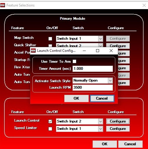
Drk, I had a second look at your description of your install. I'm sure your clutch switch is working fine and you have that wire tapped into the OEM clutch switch as it should be. I'm a little surprised your launch rev limiter did anything at all. Just skip to the posts below this.
-------------------------------------------------------------------------
I have yet to set mine up but what I recall is that the launch control is in effect when the circuit is closed. The circuit is closed when the clutch switch grounds. The clutch switch grounds when the clutch lever is pulled.
The clutch switch is supposed to be so the starter will not turn while the transmission is in gear unless the clutch lever is pulled. Does the bike start while in gear without pulling the clutch? Careful when you test that one out! Be ready to grab the clutch! If the starter doesn't turn when you hit the start button with he bike in gear and clutch lever released, the clutch switch is working as intended / OEM.
So your PC5/IM thinks the clutch lever is pulled all the time? My first guess is that maybe the pin in your clutch switch IS stuck closed. DO you ever start in gear? If you start in N all the time like I do, the pin might be stuck and you would never know it. The bike would behave normally using the clutch to shift but it would take off into a wall or something if you started it in gear! If the clutch switch pin were to be stuck in, it would also activate launch control at all times. Whatever rpm you set launch control for is where the ignition cut happens cluch lever pulled or not...in all gears and I suppose in N too...if the clutch switch pin is stuck.
With bike off:
Put ear down by clutch lever.
Pull clutch lever. You should hear the tiniest "plink" like Horton Hears a Who. TINY. plink.
No plink, no clutch switch closing. No clutch switch closing:
A)is clutch switch pin stuck in?
B) is clutch switch pin broken off, worn down or otherwise not contacting or not pushed in far enough by the adjoining surface of the lever that's supposed to push pin in?
C) is clutch fluid pressure low, not allowing lever to fully release clutch switch pin or is clutch lever throw set too small thereby keeping tension on the clutch switch pin?
D) ? something else.
If A) there's your launch control problem.
If B) better replace the clutch switch and you still got your launch control problem to figure out.
If C) bleed clutch.
If D).....? depends what that something else is. More info.
So let's say you do hear your little plink when you pull the clutch lever in. Then there should be no ground when the lever is released and I believe you should hear another little plink when you do release the clutch lever slowly. Launch control should be inactive with clutch lever released because there is no power going to ground from the clutch switch, switch is open. With lever released, clutch switch OEM wire is dead and wire positapped from clutch switch OEM wire to PC5 input SHOULD also be dead. No ground made to PC5 input, launch control inactive.
A) Does wire positapped from clutch switch OEM wire to PC5 input somehow have power in it all the time? That would do it. That power would ground to PC5 constantly and you would have perpetual launch control being there is no switch in the circuit to cut the power to ground in PC5 input.
-Are you sure you have the clutch switch OEM wire positapped at the grounding end? That is behind the clutch switch to the rear of the bike....seems unlikely you could have positapped anywhere except the grounding end of the clutch switch OEM wire but have a look. Should be a black OEM wire from clutch switch, maybe you will see one grey or silver mark on it. If the clutch switch is somehow tapped into at the positive (incoming) side, that is your problem, you have power in that wire all the time and it is grounding to the PC5 all the time so you have launch control activated all the time.
- Remove PC5 launch control wire from input. Connect red clip on test light to loose end of launch control wire. Connect black clip of test light to battery (-) terminal, battery ground screw on frame outside battery box or any reliable ground. I used a jumper wire to reach the battery ground screw on frame. Turn ignition key ON.
Test light comes on, you have power in that wire all the time and you shouldn't.
Test light doesn't come on, GOOD! There is no power and there should not be.
Pull clutch lever.
--Test light comes on, GOOD. Your connection from the clutch switch OEM wire is good.
--Test light does not come on, start bike in N. Having the ignition ON should be sufficient but might as well try with engine running just to be thorough.
-----Engine running, test light should come on when clutch lever is pulled.
-----If test light is on with clutch lever released, you have constant power in the wire that goes to the PC5 input and you should not.
--Pull clutch lever and put in gear just for kicks. Test light should have come on as soon as you pulled clutch lever but why not try it just to see what happens?
------If test light is on with engine running and before you put transmission in gear, you have costant power and this you should not have. Only with clutch lever pulled.
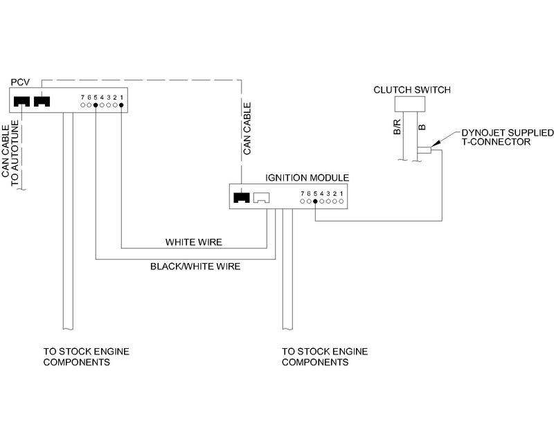
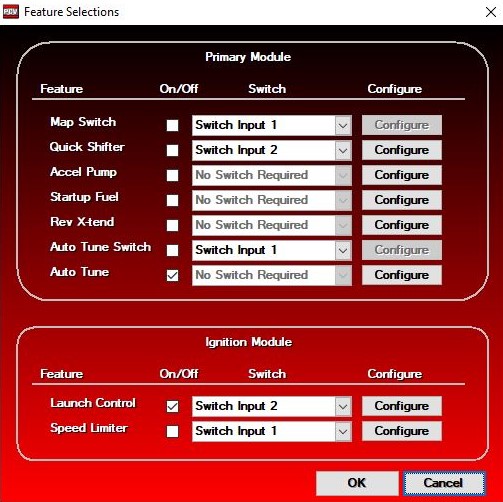
- Check that the wire which is positapped from the grounding end of the clutch switch OEM wire is in fact connected to the correct input of the PC5. This is the third hole from the main harness going into the PC5. Look at the top illustration in the IM instructions.
EVERYTHING OK with the connections between the clutch switch OEM wire and the PC5? Clutch switch works as it should?
The only other thing would be the connections between the IM harness to the PC5.
White wire from the IM harness goes to input 1. PC5 input 1 is farthest hole from the main harness of the PC5. You couldn't have screwed that one up.
Black/white wire from IM harness goes to input 5 of the PC5, third hole from PC5 main harness. In the IM instructions, the illustration appears as though the black/white wire from the IM main harness is connected to input 4. The farthest hole in PC5 from the PC5 main harness is input 1, next hole closer to main harness is input 2, next hole closer is input 3, next hole is input 4 (that's the wrong hole) and the next hole is input 5 (that's the right hole!). Shame on DJ for not fixing this illustration even after eleven years. If you're in input 4 of the PC5, that I believe, is just a digital ground. It does not connect with any of the system functions. I suppose it's just there if you have something digital that you want to ground there like an LED maybe? I asked about it. Can't remember if DJ gave the A-OK on using that for an LED but I think not. I sure would't hook up just anything in those ground inputs or you could fry the module.
Does that help? If not, more info. Chris Kelley is the guy at DJ to talk with if you can't figure this out. The normal techs have been helpful in the past but I got the impression I wasn't always getting the exact info and also, they seem to be under time demands. Chris Kelley knows everything.
* Last updated by: Rook on 2/7/2021 @ 1:18 PM *
'08 MIDNIGHT SAPPHIRE BLUE Now Deceased